EasyManua.ls Logo

Simrad MX612 - User Manual

Simrad MX612
100 pages
Print Icon
To Next Page IconTo Next Page
Loading...
ENGLISH
GN70/MX610/MX612
Operator and Installation Manual
navico.com/commercial

Table of Contents

Other manuals for Simrad MX612

Questions and Answers

  • S
    Spencer MaddoxSep 12, 2025
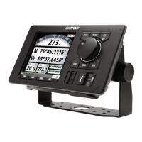
    How to adjust display brightness on Simrad MX612 Marine Equipment?
    • S
      Samuel GilesSep 12, 2025
      If the display on your Simrad Marine Equipment is dim, try pressing the power button briefly to increase the backlight brightness.
  • C
    Carl ValenciaSep 13, 2025
    What causes CAN bus failure in Simrad Marine Equipment?
    • F
      Francis MontoyaSep 14, 2025
      A CAN bus failure in Simrad Marine Equipment may be due to a poor CAN bus backbone, a defective cable or connector, or a defective CAN bus receiver in the autopilot control unit. To resolve this: 1. Check the backbone terminations. 2. Inspect cables and connectors. 3. Replace the N2K power supply or the MX61xJB junction box unit.
  • R
    Ryan MarshSep 16, 2025
    How to troubleshoot low CAN bus voltage on Simrad Marine Equipment?
    • R
      Rachael JenningsSep 16, 2025
      Low CAN bus voltage on your Simrad Marine Equipment may be improved by checking the cable length, bus load, and bus supply feeding point. If possible, determine if the issue resolves by disconnecting some units.
  • A
    alexmartinezNov 22, 2025
    What to do if Simrad Marine Equipment unit fails to detect the antenna?
    • E
      Emily CrawfordNov 22, 2025
      If your Simrad Marine Equipment unit fails to detect the antenna, follow these steps: * For N2K antenna models (GS70 or HS80), ensure the antenna is properly connected, the cable connector is in good condition, and there is no damage to the cable. * Verify that the dedicated 12 VDC supply to the N2K network is available and cycle the power to the N2K bus. * Confirm that the antenna is selected as the data source under the main Menu/Network/Sources page. * Ensure N2K terminators are installed at both ends of the NMEA 2000 bus. * For MX521A or MX575C/D antennas connected to Port 3 of the MX61xJB: 1. Ensure Port 3 of the MX61xJB is configured to match the baud rate setting of the MX antenna (4800 or 19,200). 2. Verify that MXJB Port 3 is selected as the source of position...

Summary

Introduction

GN70;MX61 x Front Panel and Keys

Details the front panel layout and function of each key.

GPS;GLONASS Selection

Basic Operation

Light;Power Key

Details the functions of the POWER/LIGHT key for unit control and display brightness.

MOB (Man-Over-Board);Mark Key

Main Pages

POS Page

Details the three POS pages showing position, altitude, depth, and trip data.

NAV Page

Describes the three NAV pages showing navigation data like range, bearing, and ETA.

AIS Page

Settings Dialog and Submenus

GPS Settings

Navigation Settings

Network Settings

Tools Dialog and Submenus

AIS Tool

Provides lists of AIS targets and received text messages.

Alerts Tool

Manages and controls the alert feature, including active, history, and settings.

Waypoints, Routes and Tracks Tool

AIS (Vessel Info)

System Configuration

Network Settings

Configuration of data sources, device lists, and diagnostics.

Selecting Data Sources

How to select data sources for position, navigation, and compass.

Manual Source Selection

Data Source Selection

Compass Antenna Offset

Multi-Hz Feature

GNSS Mode

DGPS Mode

Reset SIMRAD Antenna

Restore MX61 x Display to Default Settings

Waypoints, Routes & Tracks Panels

Routes

Creating a New Route

Step-by-step guide to creating a new route.

Starting a Route

Navigating with the GN70;MX61 x

Goto Menu

Start navigation to a waypoint or route using the Goto menu.

Navigate a Route

Procedure to start navigating a route.

Navigation Settings Panel

Panel for configuring navigation parameters like XTD limit and arrival radius.

Navigation Panels

NAV Panel

Shows navigation data like heading, distance, speed, and ETA.

POSition Panel

HDG Screens

Data Source Selection

Methods for selecting auto or manual data sources for heading.

Advance Data Source Selection

Heading Reference Control

Using AIS (PLOT)

Viewing Information about AIS Targets

Vessel Settings Panel

Alert System

Acknowledging a Message

Alert Settings

List of Alert and Warning Messages

Using the Simulator

Maintenance

Trouble Shooting

Software Upgrades

CDU Software Update (USB Method)

Step-by-step guide for updating the CDU software via USB.

Junction Box Software Update (USB Method)

Procedure to update junction box software via the display USB.

Software Update Procedure using a PC

List of Components

Mounting

Bracket Mount (Option)

Antenna Systems

MX61 xJB Junction Box

Wiring

System Wiring Principles

Explains the system components and basic wiring principles for CAN bus.

CAN Bus

Network Backbone Installation

Powering Display Units

IEC61162-1;2 (NMEA 0183) Devices

Alarm Interface

External MOB Command

Sensor Connections

PCB Terminals

GPS Compass System Diagram

Junction Box Antenna Connection

HS80;HS80 A N2 K Connection

Specifications

GN70;MX61 x Control Unit

Technical specifications for the GN70/MX61x control unit.

MX61 xJB Junction Box

Smart Antenna Unit Specifications

Connector Pinouts

Supported Data

GPS and GNSS Modes NMEA 0183 Messages

List of Abbreviations

Simrad MX612 Specifications

General IconGeneral
Channels72
Update Rate1 Hz
SBASYes
ProtocolsNMEA 0183, NMEA 2000
Power Supply10-32 V DC
Operating Temperature-15°C to +55°C
Storage Temperature-25°C to +70°C
Dimensions144 x 144 x 86 mm (without bracket)
Weight0.5 kg
Waterproof RatingIPx6
Receiver TypeGPS
Position Accuracy2.5 m
Chart CompatibilityC-MAP

Related product manuals