EasyManua.ls Logo

Simrad MX610 - User Manual

Simrad MX610
100 pages
Print Icon
To Next Page IconTo Next Page
Loading...
ENGLISH
MX610/MX612
Operator and Installation Manual
navico.com/commercial
www.busse-yachtshop.de | info@busse-yachtshop.de

Table of Contents

Questions and Answers

  • M
    Michael McintyreAug 13, 2025
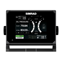
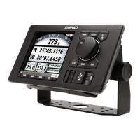
    How to fix Simrad Marine Equipment MX610/MX612 unit that fails to turn ON?
    • M
      Mrs. Angela JohnsonAug 14, 2025
      To address a unit that fails to turn ON, ensure the power cable is properly connected to the back of the MX610/MX612 and that the 12-24 VDC power is active. Note that the unit typically requires about 30 seconds to reboot after power is reconnected. Also, inspect the power cable's in-line fuse (or circuit-breaker) and replace it if it's blown. Using a voltmeter, confirm that the 12-24 VDC supply is present on the power cable connector pins. If the issue persists, consider replacing the MX610/MX612 unit.
  • J
    Jill VillegasAug 17, 2025
    What to do if Simrad Marine Equipment AIS targets are not detected?
    • A
      april33Aug 17, 2025
      If AIS targets are not being detected, first verify that an AIS transponder is connected to the N2K bus and that the AIS transponder is turned on. Inspect the VHF antenna, coaxial cable, and connectors for any signs of damage. If the problem continues, consider replacing the AIS transponder.
  • M
    Margaret DavisAug 25, 2025
    Why is True Heading not displayed on my Simrad Marine Equipment?
    • G
      Guy LyonsAug 26, 2025
      If true heading is not displayed on your Simrad Marine Equipment, verify that the data source selected under the MENU/Data sources/ Compass is either the HS70/HS80/MX575C or Gyro. Perform an auto-select procedure or manually select the correct GPS compass unit. If the problem persists, replace the GPS compass antenna unit.
  • N
    Nicole BowmanAug 28, 2025
    How to troubleshoot a CAN bus failure on Simrad Marine Equipment?
    • J
      Jennifer ShafferAug 28, 2025
      If you are experiencing a CAN bus failure with your Simrad Marine Equipment, check the following: 1. Ensure that the backbone terminations are correct. 2. Inspect the cables and connectors for any defects. 3. Replace the N2K power supply or the MX61xJB junction box unit.
  • E
    Elizabeth NormanSep 1, 2025
    How to brighten a dim display on Simrad Marine Equipment?
    • T
      Taylor HurleySep 1, 2025
      If the display on your Simrad Marine Equipment is dim, try pressing the power button momentarily to increase the backlight brightness.
  • Y
    ywilliamsSep 4, 2025
    What does a red flashing power button and black display mean on Simrad Marine Equipment?
    • T
      Tina SmithSep 5, 2025
      If the power button on your Simrad Marine Equipment is flashing red and the display is black, it indicates that the local supply voltage is either missing or below 5 V. Check the local power supply, connections, and fuses. To resolve this, press and hold the power button for 5-6 seconds to completely turn off the unit, then repower it by pressing the power key again.
  • G
    Gloria KingSep 8, 2025
    What causes low CAN bus voltage on Simrad Marine Equipment?
    • C
      Christopher NicholsSep 8, 2025
      If you are experiencing low CAN bus voltage with your Simrad Marine Equipment, check the cable length, bus load, and bus supply feeding point. If possible, check if the fault disappears by disconnecting some units.
  • A
    Amber CarterNov 20, 2025
    What to do if Simrad Marine Equipment unit fails to detect the antenna?
    • M
      millernicoleNov 20, 2025
      If your Simrad Marine Equipment unit fails to detect the antenna, follow these steps: * For N2K antenna models (GS70 or HS80), ensure the antenna is properly connected, the cable connector is in good condition, and there is no damage to the cable. * Verify that the dedicated 12 VDC supply to the N2K network is available and cycle the power to the N2K bus. * Confirm that the antenna is selected as the data source under the main Menu/Network/Sources page. * Ensure N2K terminators are installed at both ends of the NMEA 2000 bus. * For MX521A or MX575C/D antennas connected to Port 3 of the MX61xJB: 1. Ensure Port 3 of the MX61xJB is configured to match the baud rate setting of the MX antenna (4800 or 19,200). 2. Verify that MXJB Port 3 is selected as the source of position...

Summary

1 Introduction

MX610;MX612 Front Panel and Keys

Describes the physical buttons and their functions on the unit.

MX610;MX612 Screens

Describes the main display elements and status indicators.

2 Basic Operation

Light;Power Key Functions

How to turn the unit on/off and adjust display backlight.

MENU Key and Dialog Boxes

Accessing menus, navigating options, and interacting with dialogs.

MOB (Man-Over-Board);Mark Key

Functionality for marking position and activating MOB.

Hot Keys Overview

POS Key Navigation

Displays position information screens (POS1, POS2, POS3).

NAV Key Navigation

Displays navigation information screens (NAV1, NAV2, NAV3).

HDG Key Navigation

Displays heading information screens (HDG1, HDG2).

AIS Key Functionality

Displays the AIS plot screen showing vessel and target information.

3 Menu Overview

Settings Dialog and Submenus

Overview of system settings and their logical grouping.

Major Settings Categories

GPS, Navigation, Network, System, Tracks, and Units settings.

Tools Dialog and Submenus

AIS, Alarms, and Satellite Tools

Tools for accessing AIS info, managing alarms, and viewing satellite status.

Waypoints, Routes, Tracks, and Trip Log Tools

Tools for creating/managing WPT/Rte/Trk and tracking voyage data.

4 Tools Page

AIS, Alarms, Satellites, WPT;Rte;Trk, Trip Log Tools

Consolidated list of available tools for various functions.

Vessel Information and Alarm Management

Viewing AIS data, managing alarms, and satellite status.

Waypoint;Route;Track and Trip Log Management

Managing waypoints, routes, tracks, and viewing trip logs.

5 System Configuration

General Setup and Network Settings

Initial setup, network configuration, and data source selection.

Antenna Setup and Baud Rate Configuration

Manual antenna setup and baud rate adjustment procedures.

Network Device List and Group Selection

Managing N2K devices, group settings, and SimNet configurations.

Baud Rate Changes and Diagnostics

Adjusting NMEA baud rates and checking network diagnostics.

Compass Antenna Offset Configuration

Compensating for compass antenna offset for accurate heading.

NMEA 0183 Output Configuration

Configuring NMEA 0183 output via Ethernet and junction box ports.

Printer Output Control and Settings

Controlling and configuring printer output settings.

Restore MX61 x Display to Default Settings

6 Waypoints, Routes & Tracks

Tracks Management

7 Navigating with the MX610;MX612

Goto Menu and Route Navigation

Starting navigation to waypoints or routes using the Goto menu.

8 HDG Screens

9 Using AIS (PLOT)

10 Alarm System

11 Using the Simulator

12 Maintenance

Trouble Shooting Common Issues

Common issues and their corrective actions for troubleshooting.

Software Upgrades

CDU Software Update Procedures

Procedures for upgrading software via USB memory stick or PC.

MX61 xJB Junction Box Software Update

Procedure to update junction box software via the display USB.

14 Mounting

Bracket Mount Option Procedure

Procedure for optional bracket mounting of the control unit.

15 Wiring

16 Specifications

Simrad MX610 Specifications

General IconGeneral
Update Rate10 Hz
SBASYes
Power consumption5 W (typical)
GNSS signalsGPS, GLONASS, Galileo, BeiDou
InterfacesNMEA 2000, Ethernet
Operating temperature+55°C
GPS ReceiverBuilt-in

Related product manuals