Do you have a question about the Simrad GC80 and is the answer not in the manual?
Introduces the GC80/GC85 Dual Gyro systems and their capabilities.
Details important safety and operational precautions for system use.
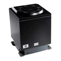
Lists and illustrates the main units comprising the GC80/GC85 Dual Gyro system.
Explains the serial signal outputs for repeaters and signal selection options.
Describes the Dual Control unit's panels and individual/dual system operation.
Details the identical control panels for each master compass and their buttons.
Explains the panel for switching between compasses and displaying information.
Outlines individual operation of gyro compasses and dual system configuration.
Provides procedures for powering the gyro compass system on and off.
Step-by-step guide to safely power down a gyro compass.
Instructions for initiating and terminating the dual operation mode.
Details how to adjust display brightness and contrast on control panels.
Explains how to set an automatic timer for the change over panel backlight.
Describes how to view current system settings via the DISP button.
Guidance on verifying and adjusting system settings during operation.
Explains how vessel speed and earth rotation affect heading and how the system corrects it.
Details the function that allows changing the heading by 180 degrees.
Explains how to switch between gyro compasses and external heading sensors.
Describes how alarm codes are displayed on control panels.
Procedure for silencing alarms and actions based on alarm status.
General guidelines for maintaining system safety and reliability.
Safety warnings regarding touching internal parts and electrostatic discharge.
Instructions for cleaning the unit's exterior surfaces safely.
Guidance on visually inspecting and ensuring proper connection of cables.
Checks for loose mechanical parts due to vibration or shock.
Recommends intervals for various maintenance actions like checking connectors and cleaning.
Detailed procedure for authorized personnel to replace the sensitive element.
Steps for safely replacing fuses in the Master Compass and Dual Control unit.
Guidance on safely unpacking and handling the system's components.
Instructions for mounting the GC80/GC85 system units considering environmental factors.
Procedures and kits for remotely mounting control panels.
Guidelines for selecting a suitable mounting location for the master compass.
Information on connecting power and signal cables according to wiring diagrams.
Importance of proper ground connections for all system units.
Overview of dip switches and jumpers used for system configuration.
Configuration steps to enable the use of an external heading sensor.
How to set up dip switches for the pendulum function via an external switch.
Step-by-step guide for installing the sensitive elements into the master compasses.
Procedure to check and verify the correct tilt angle of the sensitive element.
Procedure for calibrating the gyrocompass against an external reference.
Steps to configure the dual function after individual gyro compasses are set up.
How to set the alarm threshold for heading difference between gyro compasses.
Explains the purpose of the Extension menu for accuracy settings.
Provides instructions on how to navigate and operate the Extension menu.
Lists and describes parameters available within the Extension menu.
Lists settling time, settle point error, and other accuracy parameters.
Covers follow-up speed, gimbal freedom, power, and consumption.
Details serial input signal formats and parameters for GPS, external heading, and LOG.
Specifies serial output signal formats and frequencies for gyro and external sensors.
Provides height, width, depth, and weight for the master compass and control unit.
Details voltage input requirements and power consumption figures.
Covers enclosure material, color, temperature ranges, and gimbal freedom.
Lists available mechanical drawings and wiring diagrams for the system.
Lists part numbers for GC80 master compass, sensitive element, and control unit.
Lists part numbers for GC85 master compass, sensitive element, and control unit.
Details optional equipment such as flush mounting kits and extension cables.
Lists and details pin assignments for the GTERM board's TB1 and TB2 connectors.
Lists and details pin assignments for the DTERM board's TB21 connector.
Overview of boards in the control unit with jumpers and dip switches for configuration.
Jumper settings for GPOWER boards related to over-current limits and power supply.
Jumper settings for the GTERM board, specifically for gyro system configuration.
DIP switch settings on SCC boards for control unit type, sensor connection, and serial format.
DIP switch settings on the SCOIF board for external sensor connection and system change.
DIP switch and jumper settings on the PCC board for HDM function and sensor input.
Explains how the GC80/85 system generates and indicates alarms.
Actions to take for fault finding when alarms are generated.
Lists alarm codes, content, and possible causes for individual gyro compasses.
Lists alarm codes, content, and possible causes for the dual system operation.
| Type | Gyro Compass |
|---|---|
| Power Supply | 24 V DC |
| Operating Temperature | -15°C to +55°C |
| Heading Resolution | 0.01° |
| Heading Repeatability | ±0.1° |
| IP Rating | IP66 |
| Storage Temperature | +70°C |
| Interfaces | NMEA 0183 |
| Humidity | 95% non-condensing |