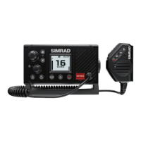
5.3 Second Receiver PCB Assembly
Refer to drawing number E03209.
The second receiver is connected to the main receiver at the power splitter L10, C215,
C214 and R205. The basic circuitry is the same as the receiver section of the main
receiver. L300, L301 and associated capacitors form the input bandpass section, prior to
the RF amplifier TR300. A second bandpass section is formed by L302 and L303, which
couple into the mixer at the source of TR301. Low side injection from the local oscillator is
fed into the gate. The output at 17.9MHz passes through the crystal filter XTAL300 and
XTAL301 to the second IF stage, IC300. Demodulated audio is buffered by IC302a.
TR304 and XTAL304 form the reference oscillator for the synthesiser, IC301. Data from
the front panel is fed from Clock, Data and Enable 2. C350, C355 and R345 form the
basic loop filter to control the frequency of the local oscillator, TR303, by varactor VC301.
The output of the local oscillator is buffered by TR302 before being coupled to the mixer
through band bass filter L307 and L308.