DC Inverter Duct Type Air Conditioner Installation and Operation Manual
37
2. The installation site must have good ventilation, so that the outdoor unit can take in and exhaust enough
air. Ensure that there is no obstacle for the air intake and exhaust of the outdoor unit. If there is any obstacle
blocking the air intake or exhaust, remove it.
3. Place of installation shall be strong enough to support the weight of outdoor unit, and it shall be able to
insulate noise and prevent vibration. Ensure that the wind and noise from the unit will not affect your neighbors.
4.Avoid direct sunshine over the unit. It is better to set up a sun shield as the protection.
5. Place of installation must be able to drain the rainwater and defrosting water.
6. Place of installation must ensure the machine will not be buried under snow or subject to the inuence of
rubbish or oil fog.
7. The installation site must be at a place where the air exhaust outlet does not face strong wind.
8.2 Installation of Indoor Unit
8.2.1 Selection of Installation Site
1. Ensure the top hanging piece has strong strength to withstand the weight of the unit.
2. The drainage pipe has convenient ow of water.
3. There is no obstacle blocking the air intake and exhaust outlet, so as to ensure sound air circulation.
4.The installation spaces required by the drawing must be ensured, so as to provide enough space for the
service and maintenance.
5. The installation site must be far away from heat source, leakage of inammable gas or smoke.
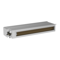
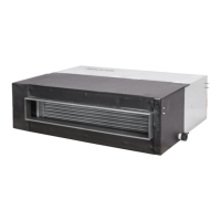
6. The indoor unit is of ceiling mount (indoor unit is hidden inside the ceiling).
7. The indoor and outdoor units, the power cable and the connecting electrical lines must be at least 1 meter
from any TV set or radio. This is to avoid image interference or noise of the TV set or radio. (Even if the
distance is 1 meter, noise can also exist if there is strong electric wave.)
8.2.2 Installation of Indoor Unit
1. Insert a M10 expansion bolt into the hole. Drive a nail into the bolt. Refer to the profile dimensions
drawing of the indoor unit for the distance between the holes. Refer to Fig. 38 for the installation of the
expansion bolt.
Fig.38 Fig.39
2. Install the hanger onto the indoor unit as Fig.39 shows.
3. Install the indoor unit at the ceiling as Fig.40 shows.
Fig.40
Precautions for unfavorable installation:
1. The preparation of all pipes (connecting pipes and drainage pipes) and cables (connecting lines of