26
Installation and Maintenance
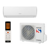
Fig.9
Fig.10
Fig.11
Fig.12
8.7 Electrical Wiring
assembly. Stick the sponge and foam assembly with double faced
adhesive tape (prepared by user) (See Fig.10, Fig.11).
6.Install the foam assembly on the air duct assembly. Use 4 screw
bolts to x the air duct assembly onto the mounting plat.
After connecting the outdoor unit with indoor unit, check whether
the foam assembly has come loose (See Fig. 9).
Make sure that all power supply to the unit is disconnected before
performing any work on the unit to avoid the possibility of shock or
injury and/or damage to the equipment. When the interior ceiling
assembly frame is properly secured to the roof top air conditioner,
the following electrical connections must be performed.
1. As shown in Fig.12, the outdoor unit has two sets of outgoing
wires, which are power cord (high current) and the control signal
wires respectively. The former one should be directly connected to
the power supply terminal while the latter one should be connected
to the control signal wire of the indoor unit.
foam
wind-path
foam
sponge(Num4,5mm)
foam(Num 4,14mm)
foam(under)
wind-path
Gasket
installation board
Thickness of vehicle
roof is from 30mm-80mm
bubble
4 bolt
4 bolt
(Max torque is from
2.3Nm~2.5Nm)
WARNING
2. As shown in Fig.13, the indoor unit has one set of control signal
wires, with 1 wiring terminals in total.
3. Connect the docking terminals of indoor unit and outdoor unit,
see Fig.14.
outdoor connect wire
outdoor
electrical
wire
indoor electrical wire
display board
Fig.13
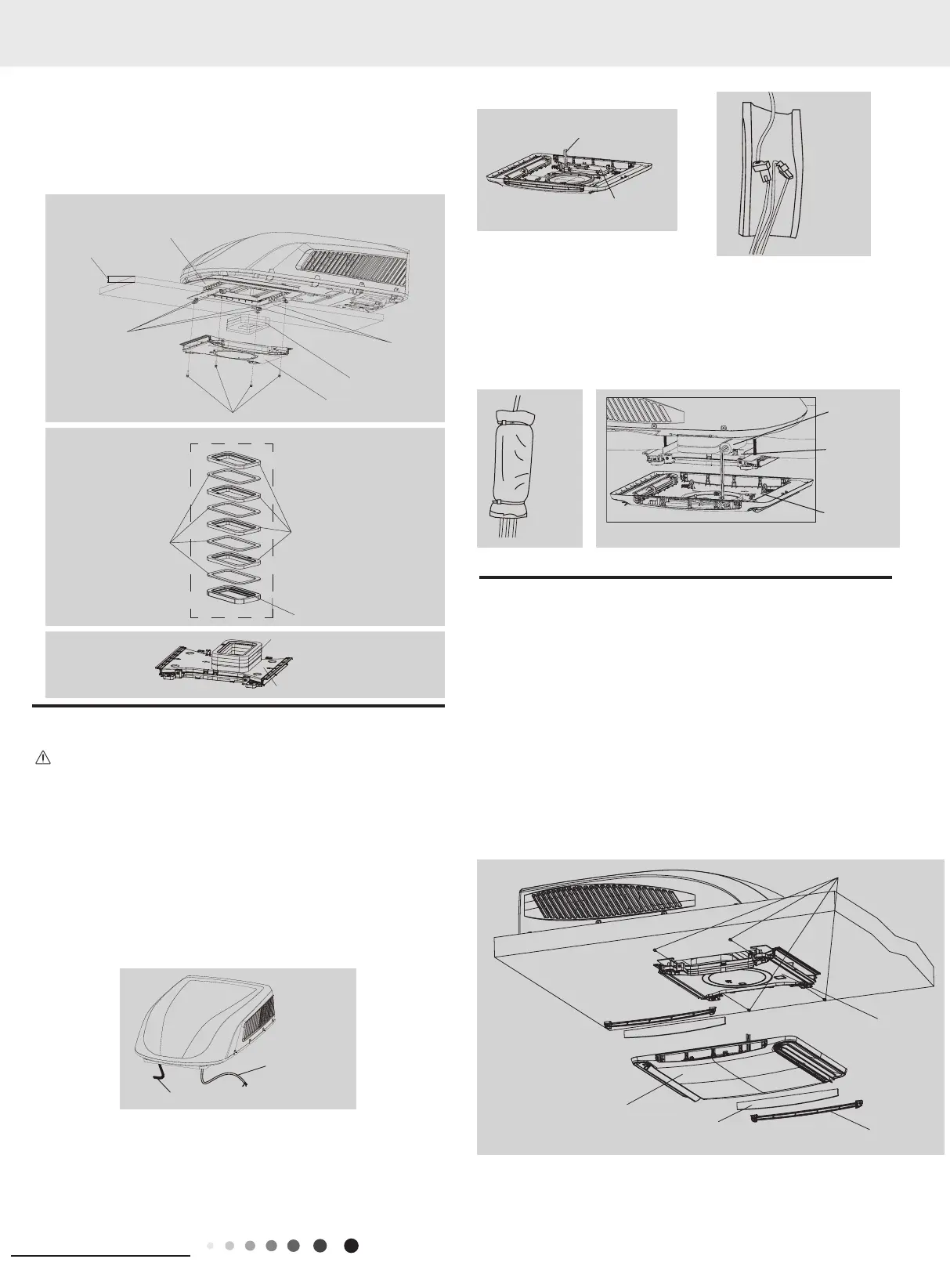
Fig.15
Fig.14
4. Use protective sleeve to wrap the wiring terminal, stick the
protective sleeve and then use cable tie to bundle them tightly.
Note:
1. The fixing position of cable must be at both ends of wiring
terminal.
2. Before installing the front panel of indoor unit, put the thermal
insulating jacket on top of the air duct.
front panel
Insulating
sheath
wind-path
Fig.16
Fig.17
8.8 Completing The Installation
To complete the installation and system checkout requirements, the
following steps must be performed.
1. Check the thermostat position. Make sure the thermostat is
routed through the holding guide and is not touching any metal
surface
.
2. Secure the ceiling grille to the ceiling assembly wind-path with 4
screws. (see Fig.17).
3. Install the healthy lter and air intake grill. Press “PUSH” and
lock with clasps.
4. Switch on the power supply and check the unit work or not.
5. Once the indoor unit is assembled, if the gap between the panel
and the top of vehicle is not even, please ask the manufacturer to
adjust it according to the assembly status.
4 screw
wind-path
front grill
front panel
filter
 Loading...