User Manual of A90 Series Inverter
16
Main
frequency
switching
DI: 51~56
0: digital frequency
setting F00.07
1: AI1*F00.16
2: AI2*F00.16
4: keyboard
potentiometer
0
1
2
3
Gain of
main
frequency
source
F00.10
Multi-segment
speed terminal
DI: 14~11
0
n=1,2,…,15
Speed of the n
th
segment
F08.00~F08.14
Options of main
frequency source
A
F00.04
None
Valid
F00.07
AI1
AI2
Communication
+
+
6: SCI*F00.16
5
UP/DOWN
setting
+
+
7: SCI
4
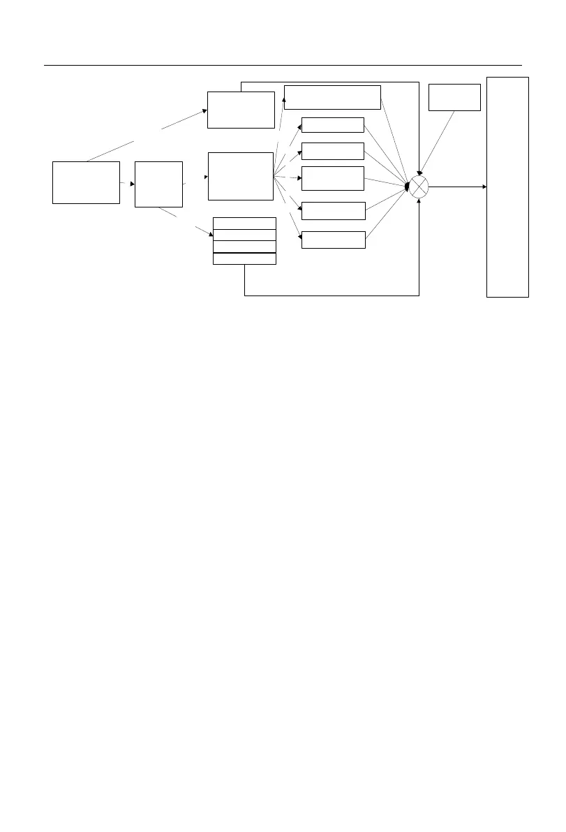
Fig. 1-2 Schematic diagram of Setting of Main Frequency Source A
As shown in Fig. 1-2, it is necessary to comprehensively consider the digital terminal
setting and its status during the setting of the main frequency source A. Depending on the
terminal settings, multi-segment speed operation can be performed or digital, analog, pulse
or communication settings can be applied directly.
If the terminals are unavailable, the current setting channel is determined by the
function code F00.04, and final settings are obtained through UP/DOWN setting
calculation.
 Loading...