User Manual of A90 Series Inverter
17
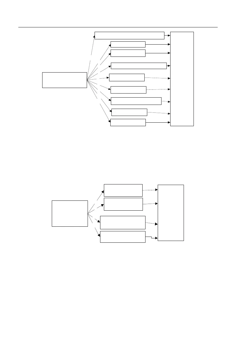
0: digital frequency setting F00.07
1: AI1*F00.16
2: AI2*F00.16
4: keyboard potentiometer
0
1
2
4
Gain of
auxiliary
frequency
source
F00.11
Options of auxiliary
frequency source B
F00.05
6: SCI*F00.16
6
10: process PID
11: simple PLC
10
11
7: SCI
7
8: digital potentiometer
8
Fig. 1-3 Schematic Diagram of Setting of Auxiliary Frequency Source B
As shown in Fig. 1-3, the current setting channel is determined directly by the function
code F00.05 during the setting of the auxiliary frequency source B, and the process PID and
simple PLC can be involved in the setting.
0: main A +
auxiliary B
1: main A -
auxiliary B
2: max (main A,
auxiliary B)
3: min (main A,
auxiliary B)
0
1
2
3
Gain of
main and
auxiliary
frequency
source
F00.12
Options of main
and auxiliary
operation
F00.08
Fig. 1-4 Schematic Diagram of Setting of Main and Auxiliary Operations
As shown in Fig. 1-4, main and auxiliary operations are divided into four types, in
which main and auxiliary settings are valid.
Torque setting mode with the motor current as controlled target
The digital setting, analog input setting, high-speed pulse input setting, communication
setting, digital potentiometer setting or multi-segment torque setting can be applied. Fig.
1-5 details the input modes of A90 series inverter based on the torque setting.
 Loading...