User Manual of A90 Series Inverter
211
In order to meet different needs, the inverter also supports communication timeout and
response delay during the communication based on the Modbus protocol.
Modbus
communicat
ion timeout
0.0 to 60.0; 0.0: invalid (also valid
for master-slave mode)
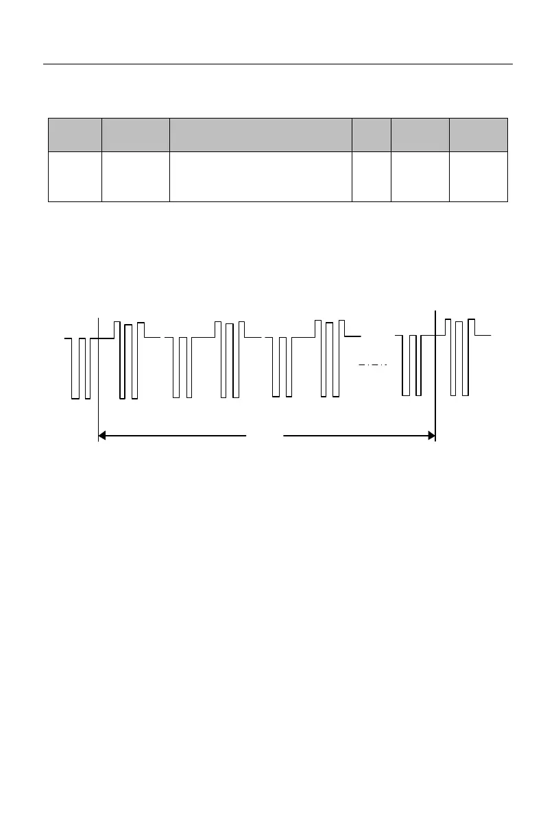
As shown in Fig. 7-29, the communication time interval
△
t is defined as the period
from the previous reception of valid data frames by the slave station (inverter) to next
reception of valid data frames. If
△
t is greater than the set time (depending on the function
code F10.03; this function is invalid if set to 0), it will be regarded communication timeout.
1#
Send
Return
2#
Return
3#
Send
Return
1#
Send
Return
△t
Fig. 7-29 Schematic Diagram of Communication Timeout
Example of this function: If the master station must send data to a slave station (e.g. #1)
within a certain period, you can use the communication timeout function of #1 slave station
and set F10.03>T. The communication timeout fault will not be triggered during normal
communication. However, if the master station does not send data to #1 slave station within
the specified time T, and this lasts for more than the set value of F10.03, a communication
fault (E16) will be reported. Once informed of the “communication fault of #1 slave
station”, the staff can conduct troubleshooting.
★
The set value of F10.03 must be greater than the set time T, but must not be too
large, in order to avoid adverse effects arising from too long operation in the fault status.
★
F10.03 should be set to be invalid under normal circumstances. This parameter
will be set only in the continuous communication system to monitor the communication.
 Loading...