User Manual of A90 Series Inverter
59
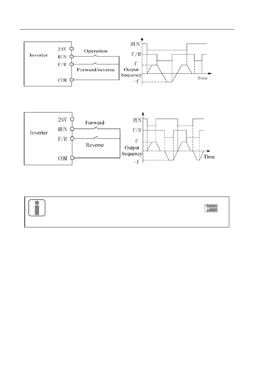
(a) Wiring diagram of two-line control (F00.03=0) (b) Forward/reverse control logic
(F04.19=0, F00.03=0)
(c) Wiring diagram of two-line control (F00.03=1) (d) Forward/reverse control logic
(F04.19=0, F00.03=1)
Fig. 5-2 Two-line Control
When the start/stop value of F00.03 is set to 0 or 1, even if the terminal RUN
is available, the inverter can be stopped by pressing the STOP key
or
sending an external stop command to the terminal. In this case, the inverter
will not be in the running status until the terminal RUN is disabled and then enabled.
Three-line control:
F00.03=2: the terminal RUN controls forward running, the terminal Xi is for stop,
and the terminal F/R is in the reverse status.
The terminal RUN is normally ON for forward running, and the terminal F/R is
normally ON for reverse running, with valid pulse edges. The terminal Xi is normally
closed for stop, with the valid level. When the inverter is in the running status, press Xi to
stop it. In the case of deceleration to stop (F04.19=0), the logic diagram is as shown in Fig.
7-2 5-3(b). The terminal Xi is for “three-line running and stop control” as defined by
F02.00 to F02.04.
F00.03=3: the terminal RUN is for running, Xi for stop and F/R for
forward/reverse control.
The terminal RUN is normally ON for running, with the valid pulse edge, F/R for
forward/reverse switching (forward in the OFF status and reverse in the ON status), and Xi
is normally OFF for stop, with the valid level. In the case of deceleration to stop
 Loading...