User Manual of A90 Series Inverter
39
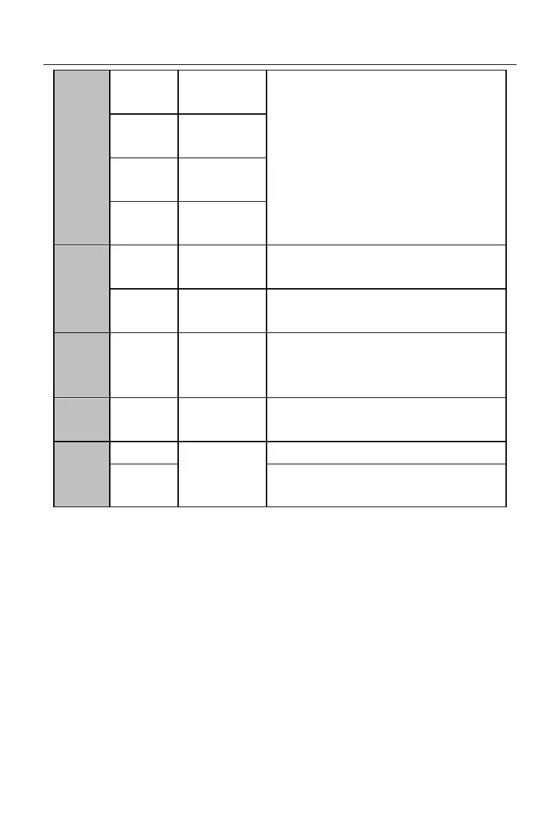
Multi-function
input terminal 2
Multi-function
input terminal 3
Multi-function
input terminal 4
Multi-function
input terminal 5
Output range: DC 0-10V/0-20mA
Open output
terminal of
collector
Open output of collector
Maximum output voltage: DC24V
Output current: 50mA
EA-EC: Normally open
EB-EC: Normally closed
RS-485
communication
terminal
positive terminal of 485 differential signal
negative terminal of 485 differential signal
Note: 1) For the A90-4T017B model and below, connect the terminals COM and GND
internally.
3.3.3
Wiring of analog input terminal
3.3.3.1
Wiring of AI1 and AI2 terminals with analog voltage signal:
When the AI2 terminal is in the mode of analog voltage signal input, the switch S2 on
the terminal block is set to the voltage mode, as shown in Fig. 3-12.
When the analog voltage input signal is powered by an external power supply, the
wiring of terminals AI1 and AI2 is shown in Fig. 3-12-a.
When the analog voltage input signal is sent by a potentiometer, the terminals AI1 and
AI2 are connected as shown in Fig. 3-12-b.
 Loading...