User Manual of EM730/EM730E Series Inverter
315
Average Braking
Current I
av
(A)
Applicable
Inverter Power
(kW)
Energy
consumption
braking
Energy
consumption
braking
★
When BR100-160 works with the minimum resistance, the braking unit can work
continuously at the braking frequency D=33%.
In the case of D>33%, intermittent operation will be performed; otherwise, the
over-temperature protection will be enabled.
10.2.1
Selection of Connecting Wires
Since all braking units and braking resistors work at high voltage (>400VDC) and in the
discontinuous status, please select appropriate wires. See Table 4-29 for the wiring
specifications of the main circuit. Use the cables with the conforming insulation levels and
cross-sections.
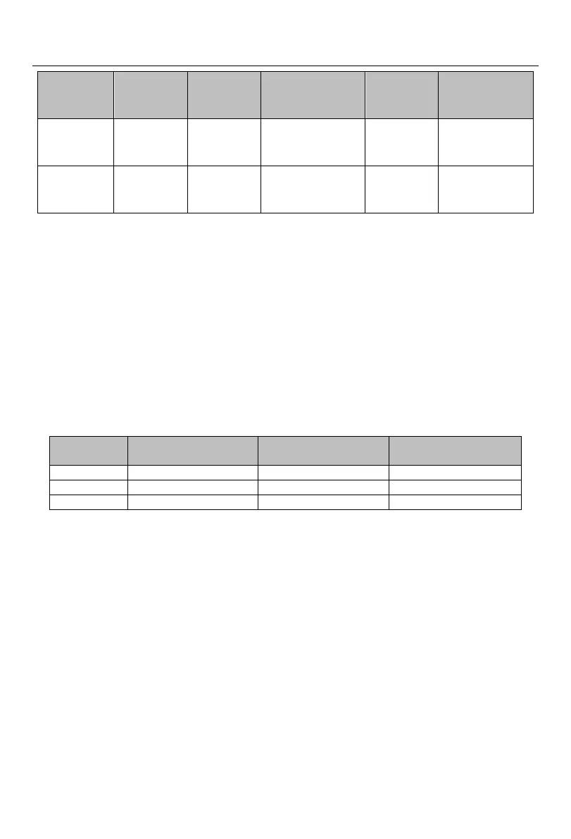
Table 4-29 Wire Specifications of Braking Units and Braking Resistors
Average Braking
Current I
av
(A)
Peak Braking Current
I
max
(A)
Cross-section (mm
2
) of
Copper-core Cable
Flexible cables have higher flexibility. Because cables may be in contact with
high-temperature devices, it is recommended to use copper-core and heat-resistant flexible
cables or flame-retardant cables. The braking unit should be close to the inverter as much as
possible and no more than 2m far away from the inverter. Otherwise, the DC-side cables should
be twisted and used with magnetic rings to reduce radiation and inductance.
The lengths of connecting wires of the braking unit, braking resistor and inverter are shown
in Fig. 4-19.

 Loading...
