User Manual of EM730/EM730E Series Inverter
318
≥3.5 characters
Start
8 digits
Address
8 digits
Function
code
N*8 bits
Data
2*8 bit
CRC check
≥3.5 characters
End
RTU message
PDU
2*8 bit
Address
of
register
2*8 bit
Number
of
registers
2 * number of registers * 8 bits
Register content
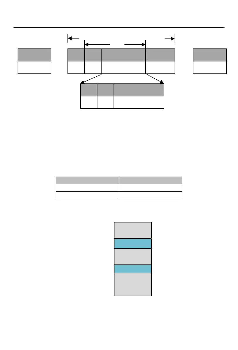
Fig. 12-20 Schematic Diagram of Message Frame in RTU Mode
The RTU message includes the address code, PDU (Protocol Data Unit) and CRC[3
]
check.
The PDU includes the function code and data part (mainly including the register address,
number of registers, register content and the like; the detailed definitions of function codes are
different, as shown in 11.3.3Function
code
).
[3]: the low byte of CRC check is in front of the high byte.
11.3.2
Address code
11.3.3
Function code
The classification of MODBUS function codes is shown in Fig. 12-21.
Common function
code
User-defined
function code
Common function
code
User-defined
function code
Common function
code
1(0x1)
65(0x41)
72(0x48)
127(0x7F)
100(0x64)
110(0x6E)
Fig. 12-21 Classification of MODBUS Function Codes

 Loading...
