11
High Speed Overlock Machine | Instructions Manual and Parts List
3.6.3
Looper
Thread Control
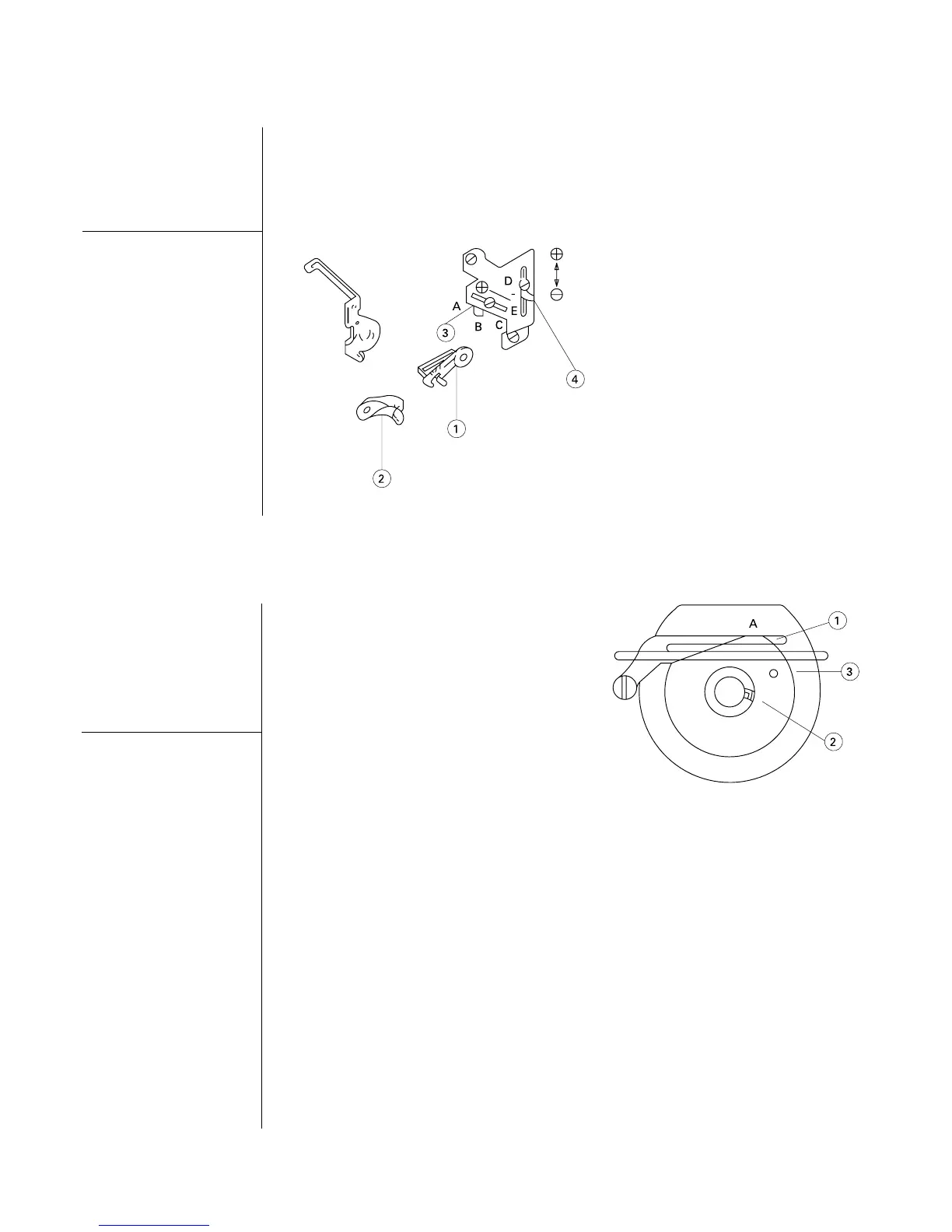
Forthetypeofstitch512,whenAd-
justguide ‘1’ and ‘2’ asfollowsthe
looperontherightisattheleftfar
end,adjust‘1’ and ‘2’inlevelwith
thedottedmark,asongure12.
Forthetypeofstitch503and505,
move the guides to the lowest
pointandadjust ‘1’ and ‘2’ inlevel
withthecontinuousline.
Adjust guide ‘3’ as follows:
•Position‘A’:forstretchythread
•Position‘B’:forseamingandblind
stitchhemming
•Position‘C’:stitchtype512
Adjust guide ‘4’ as follows:
•Position‘D’:forstretchythread
•Position‘E’:forseamingandblind
stitchhemming.
Figure 12
3.6.4
Chain Looper
Thread Cam
Control
When the needle is on high posi-
tion,mark ‘A’ mustbealignedwith
the thread guide bracket ‘1’, as
shownongure13.
Release screw ‘2’ and the thread
cam‘3’. Turnitclockwiseforquick
releaseofthreadthroughthecam.
Figure 13
The signal (+) means
more thread and (-)
means less thread.
Note