104 73 97-26 S0100 / S0105 7
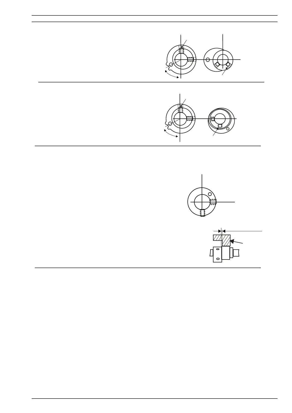
6. Turn the hand wheel in the sewing direc-
tion, so #1 point and Cam #2' fi rst screw (a) is
straight to the front (Y- direction)
7. The #4 Cam - Upper looper cam.
It should now be positioned so the centre posi-
tion between the set screws (b) and (c) is accor-
ding to the illustration (X- direction) .
8. The #2 Feed cam should remain in the same
position.
9. The # 5 Cam - Lower looper cam.
It should now be positioned so its fi rst screw (b)
is according to the illustration (X-direction).
10. Turn the handwheel in sewing direction to Set #1 point - the counter weight mark and
fastening pin, so they are lined up against the (B) screw on the casting.
11. The # 6 Cam - Feed lifting cam.
It should now be positioned so its fi rst screw (b) is accor-
ding to the illustration (X-direction).
When setting the Feed lifting cam, set it so there is a clea-
rance of 0.2~0.5 mm between it and the feed bar (D).
NOTE! Final setting of the each cam position is done when the individual setting is perfor-
med.
X = Top
Y = Front
X
YY
aa
b
X
YY
a
b
X
X
Y
0.2~0.5 mm
D