CHASSIS AND TURNTABLE ASSEMBLY
GTZZ14EJ&16EJ Maintenance Manual 37
© May 2023
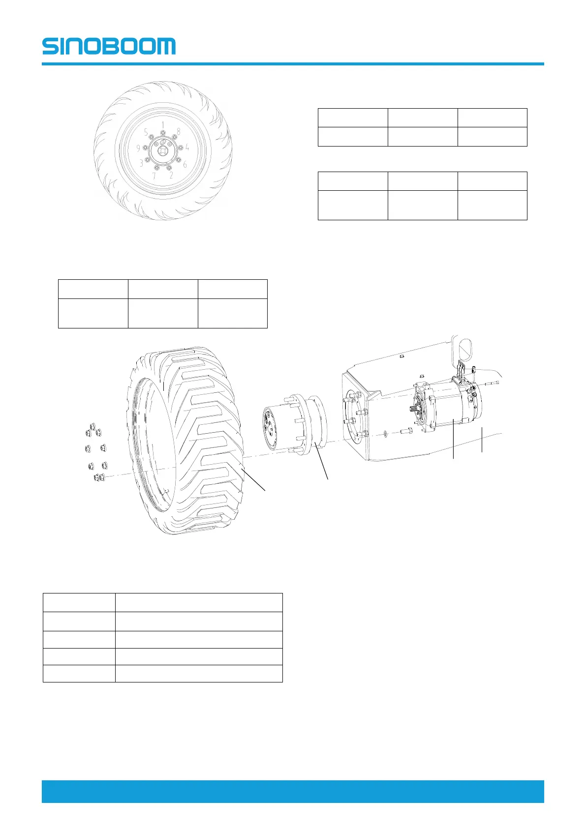
Fig 2 Diagram of wheel nuts tightening sequence
Table 5-1 Table of front wheel nuts tightening torque
First step
Second step
Third step
100Nm
(74ft-lb)
180Nm
(133ft-lb)
246Nm
Table 5-1 Table of front wheel nuts tightening torque
(Continued)
First step
Second step
Third step
(182ft-lb)
Table 5-2 Table of rear wheel nuts tightening torque
First step
Second step
Third step
100Nm
(74ft-lb)
200Nm
(148ft-lb)
283Nm
(209ft-lb)
5.3 TRAVEL DRIVE DEVICE
The travel drive device is mainly composed of the travel
reducer and travel motor.
Fig 3 Diagram of travel drive device
Table 5-3 Travel drive device
No.
Description
A
Outrigger
B Travel motor
C Travel reducer
D Tire
Check Disengaged Drive Hub Cap
The drive hub in the travel drive device can be engaged
and disengaged. The two positions can be achieved by
obversely mounting and reversely mounting the drive
hub cap, as shown below.
 Loading...