© Apr 2022 2-2 TB18 Plus&20J Plus Operation Manual
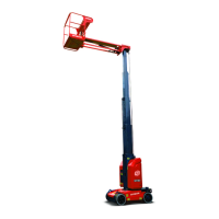
MACHINE COMPONENTS
Table 2-1
1. Platform 14. Hydraulic tank 27. AC power receptacle (optional)
2. Jib lift cylinder 15. Ground controller 28. Manual storage container (optional)
3. Jib boom 16. Oscillate cylinder 29. Footswitch
4. Slave cylinder 17. Front wheel 30. Plataform controller
5. 2nd telescopic boom 18. Steer linkage 31. Work light (optional)
6. 1st telescopic boom 19. Steer cylinder 32. Limit device (optional)
7. Base boom 20. Power plug 33. Turntable cover, LH
8. Cable track 21. Rear wheel 34. Battery
9. Main lift cylinder 22. Drive reducer 35. Slewing bearing
10. Master cylinder 23. Drive motor 36. Engine
11. Flash beacon 24. Chassis 37. Power disconnect switch
12. Counterweight 25. Turntable
13. Fuel tank 26. Turntable cover, RH
Machine positions
Stowed position:
Boom descends and retracts in place.
Non-operating position:
Boom rises at an angle not exceeding 15°, and extends
not exceeding 1.2m (3.9 ft).
Operating/raised position:
Boom rises at an angle exceeding 15°, or extends
beyond 1.2m (3.9 ft).