14
ASSEMBLY INSTRUCTIONS….cont
6.Once the belt has been set to the desired speed, re-tension the belt by tightening
bolts.
7.Close the belt guard and secure with the screw.
On page 15 is a table which will give you some idea of what speed materials should
be cut at.
1.Prior to changing the blade speed ensure the mains lead is disconnected.
2.Unscrew and remove belt guard screw and lift up the cover, this will allow access to
the belt so it can be adjusted.
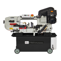
3.Loosen the motor plate lock bolt (Fig.1, A).
4.Loosen the motor slide bolts (Fig.1,B), you should
now be able to push the motor inwards to slacken
the belt off.
A
B
B
Fig.1
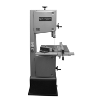
5.Move the belt to the desired speed (Fig.2).
65
Motor
45
33
22
Blade Speed m/min
Fig.2
SETTING THE BLADE SPEED
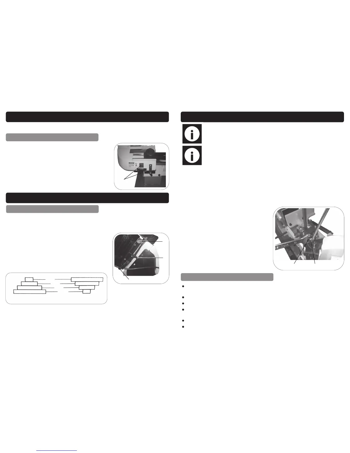
Before the bandsaw can be used the transit bolt and
bracket must be removed; this is situated at the end
of the saw bow and bed (see right picture). Once the
bracket is removed refit the head stop bolt and adjust
it’s height so as to prevent excessive pressure on the
end of cut microswitch.
Remove
REMOVING THE TRANSIT BOLT
OPERATING INSTRUCTIONS
thinner or lacquer thinner as these will damage the painted surfaces.
23
Do not used compressed air to clean the bandsaw, this can cause metal fillings
to go into the guide bearings and other parts of the bandsaw.
Always remove the metal fillings from the blade guides after use.
Wipe the bandsaw down with a dry cloth.
Check the guide bearings regularly making sure they are clean and correctly
adjusted.
Always check to make sure the wire brush properly adjusted and cleaned.
Always disconnect from the mains supply before carrying out any maintenance.
GENERAL MAINTENANCE
MAINTENANCE INSTRUCTIONS….cont
1.Raise the saw bow to the vertical position and lock it by turning the hydraulic cylinder
tap to the off position.
2.Remove the two screws holding the bearing guard plate onto the lower eccentric
shaft.
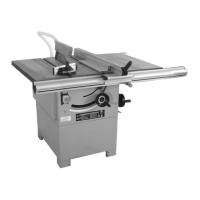
3.Loosen the nut (Fig.4,A) holding the eccentric shaft in position.
4.With a spanner turn the eccentric shaft (Fig.4,B) until there is a gap of about 0.001”,
you should just be able to slide a piece of paper between the gap.
Note: The outer bearing shaft is eccentric and is the one to adjust, the
inner bearing shaft is fixed and can not be adjusted.
Note: Never attempt to adjust the blade guide bearings whilst the ma-
chine is running, ALWAYS disconnect from the mains supply before pro-
ceeding.
Fig.4
A
B
5.Once the eccentric shaft has been adjust-
ed, retighten the nut (A) and screw the plate
back on.
6.Repeat steps 3-5 for the upper eccentric
shaft.