14
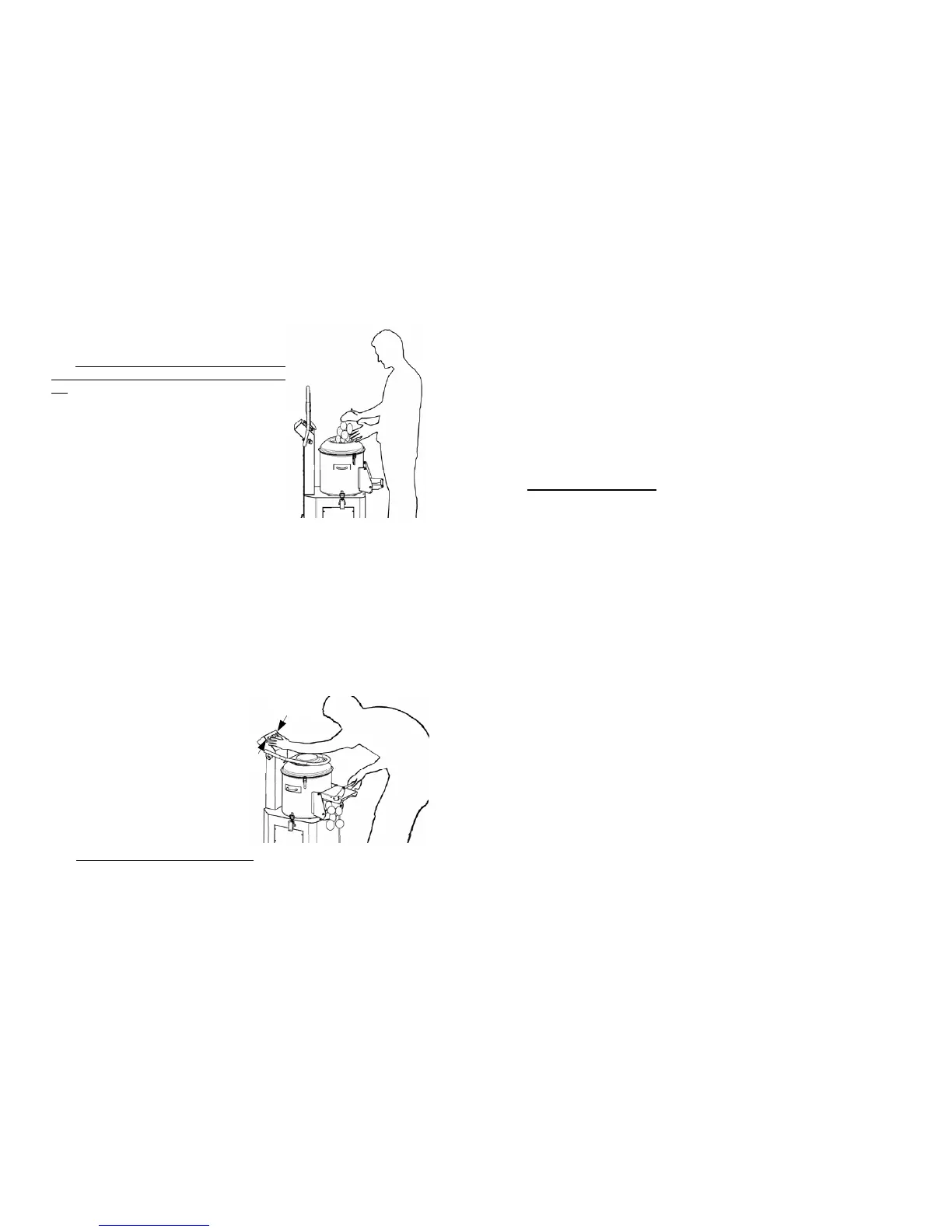
AND WORKING THE PRODUCT (see FIG.
n°10)
NB: The goods to be worked are loaded gradually
on the cap from the upper cover when the motor is
off.
Adhere to the following procedure:
1 load the product from the upper cover, making
sure that the discharge door is closed well;
2 check that the machine is not too full and that
the level of the product does not go over the a-
brasive band inside the machine;
3 close the upper cover;
4 open the water flow using the faucet on the
hopper;
Running:
1 set the desired work time with the timer
(max time 5 min.);
2 then start the machine by pressing the START pushbutton;
3 if the cover and/or discharge door are accidentally opened or moved while the
machine is running, the machine will stop; when closed press the START but-
ton;
4 open the water flow using the faucet on the hopper;
5 if the machine is outfitted with a stand with sieve, repeatedly unload the slag
tray, to avoid the water dripping.
Unloading the worked product:
(see FIG. n°11)
1 close the water faucet and put a big con-
tainer near the discharge outlet;
2 to unload the material open the dischar-
ge door, keeping it open with your right
hand; press the OUT and START
pushbutton at the same time with
your left hand; the machine will
start unloading the product by centrifu-
gal force;
3 once the unloading is complete the ma-
chine will stop by releasing the pu-
shbuttons and the discharge door;
N.B.: Avoid making an empty machine turn.
FIG. n°10 - Loading the product
FIG. n°11 -Unloading the product
START
OUT
3
CHAP. 7 - MAINTENANCE page 16
7.1 - GENERALITIES
7.2 - BELT
7.3 - FEET
7.4 - FEEDING CABLE
CHAP. 8 - DISMANTLING page 16
8.1 - PUTTING IT OUT OF WORK
8.2 - DISPOSAL
INDEX OF DRAWINGS
FIG. n°1 - Generale view of the machine page 6
FIG. n°2 - Drawings of dimensions page 6
FIG. n°3 - Package description page 8
FIG. n°4 - Discharge diagram page 9
FIG. n°5 - Serial number—technical plate page 10
FIG. n°6 - Mn electrical diagram page 11
FIG. n°7 - Tf electrical diagram page 12
FIG. n°8 - Cap rotation page 13
FIG. n°9 - Position of controls page 13
FIG. n°10 - Loading the product page 14
FIG. n°11 - Unloading the product page 14
FIG. n°12 - Dismantled machine page 15