6
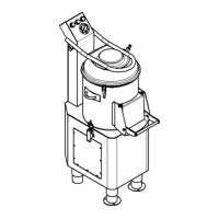
KEY:
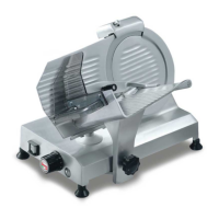
1. Pushbutton strip
2. Hopper
3. Cover block hinge
4. Pan
5. Pan block hinge
6. Maintenance door
7. Feet
8. Flanged feet
9. Structure
10. Discharge door
11. Cover
12. Feeding tap
13. Handle
14. Stand
15. Sieve
NB: there is the possibility of adding the sieve to the stand
to collect waste.
CHAP. 2 - TECHNICAL DATA
2.1 - DIMENSIONS, WEIGHT, CHARACTERISTICS ...
1.3.3 - Machine makeup
14
15
3
1
2
5
7
9
4
8
10
12
13
6
11
11
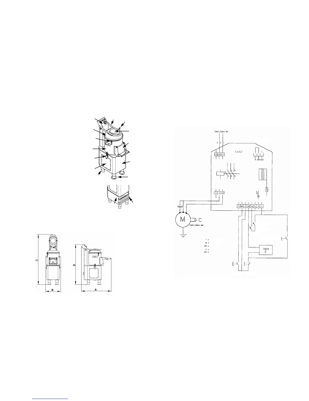
4.3 - ELECTRICAL DIAGRAMS
4.3.1 - Diagram of the single-phase electrical system
FIG. n°6 - Mn electrical diagram
FEED
TENSION CHANGE
DOOR MICROSWITCH
COVER MICRO
DISCHARGE PUSHBUTTON
GREEN/BLACK
BLUE/BLAK
RED
WHITE
BLACK
ON BUTTON OFF BUTTON