SIRS NAVIGATION LTD
COMPONENT MAINTENANCE MANUAL
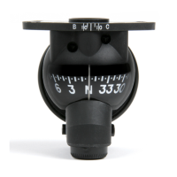
The compass must be installed with two ‘non-magnetic’ screws, with a head
diameter of dimension 6.5mm to 6.9mm.
CAUTION: THE SCREWS THAT ATTACH THE COMPASS MUST NOT
BE OVER-TIGHTENED.
NOTE: Refer to the installation drawing for detailed information.The compass
does not need electrical power to operate, other than for illumination. The
compass will operate after installation and ‘magnetic correction’.
Magnetic correction is required to correct for magnetic errors caused by
the aircraft, local components or instruments. A correction procedure for
the compass is specified in page Block 11001 Special Procedures.
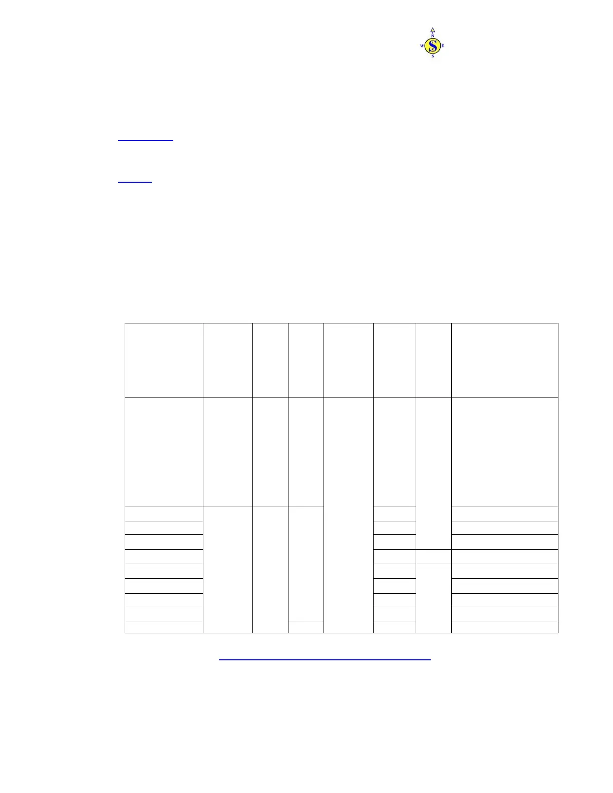
E. Leading Particulars
The leading particulars for each compass are shown in table 1 below
Code
Size
Weight
Voltage (dc)
Ambient
Operating
Temperture.
Lamp
Resistor
Body Colour
Card Legend
Colour
KCA0101W
Height: 51.0mm (2.00in)
Width: 57.5mm (2.26in)
Depth: 49.0mm (1.93in)
0.09KG
(3.5 oz)
None None White
KCA0104W
330Ω
White
KCA0104FY
330Ω
Fluorescent Yellow
KCA0105W
330Ω
Black
White
KCA0106W
330Ω
Grey White
KCA0112W
820Ω
White
KCA0113W
390Ω
White
KCA0113FY
390Ω
Fluorescent Yellow
KCA0114W
28v
47Ω
White
WL1001KCA1
Height: 57.5mm (2.26in)
Width: 57.5mm (2.26in)
Depth: 51.5mm (2.03in)
0.113KG
(4 oz)
5v
-40°C to +80°C
None
Black
White
Standby Compass - Leading Particulars
Table 1
PAGE 3
APR 10/03
34-25-21
The document reference is online, please check the correspondence between the online documentation and the printed version.