3
2. Installation and Adjustment:
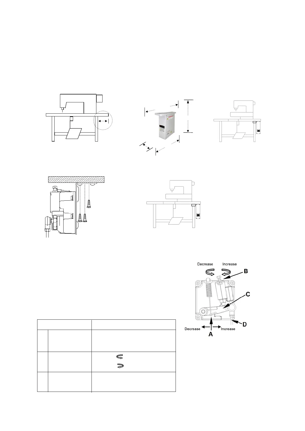
(1). Motor installation:
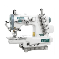
When motor and machine installed together, refer to the machine head’s instruction.
(2). Control Box Installation:
(3). Speed Control Unit Installation:
(4). Adjust the Speed Control Unit:
a). Leave 100 mm space at right b). Mounting TD under the working table c). Installation layout
100 mm
a). Keep rod in vertical, secure the unit under the table b).Installation layout
60mm
247.5mm
175.6mm
Measurement
232.6mm
Components of the speed control unit: see figure
A: Spring for toeing forward force adjustment
B: Bolt for heeling backward force adjustment
C: Treadle / Pedal arm。
D: Pitman Rod for Treadle / Pedal
Term of adjustment
Toeing forward
force adjustment
Heeling backward
force adjustment
Treadle stroke
adjustment
Adjustment result
Spring A move to right = force increased
Spring A move to left = force decreased
Bolt B turn = force decreased
Bolt B turn = force increased
Rod D secure at right = stroke is longer,
Rod D secure at left = stroke is shorter。
1
2
3
Control
box