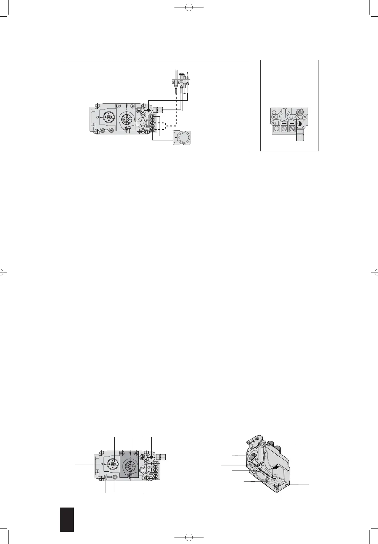
Pilot burner
TP = millivolt generator
TH = thermostat
room thermostat
mV versions
» Pilot outlet
… Main gas outlet
˛ Holes (M5) for fixing flange
¢ Valve supplementary
fixing point
£ Alternative thermocouple connection
§ Magnet unit
• Connection to the combustion
chamber
SETTINGS AND ADJUSTMENTS
All adjustments must be made on the basis of the specific characteristics of the appliance.
Check inlet and outlet pressure using the pressure test points and provided. After testing, carefully seal test
points with the provided screws. Recommended torque: 2.5 Nm.
Outlet pressure adjustment
Remove the protective plug (A). Turn the adjustment screw (B) clockwise to increase outlet pressure. After setting, fit
the plug (A) flush.
Overriding the pressure regulator
Replace the plug (A), the adjustment screw (B) and the spring (C) with the accessory (D), code 0.907.037. Torque:
1Nm.
Adjustment of gas flow to the pilot burner
Turn the screw clockwise to reduce flow.
Overriding the pilot flow adjustment function
Screw the setting screw in flush and then back off two complete turns. Then seal the setting.
Changing the gas family or group
Check that the appliance is suitable for operation with the gas family or group in question. Following the instructions
given above, adjust the outlet pressure to values given in the appliance's instruction book. With third family gases:
override the pressure regulator and gas flow adjustment to the pilot burner.
IMPORTANT:
At the end of all setting and adjustment operations, check gas seals and the efficiency of the
appliance. In particular, it is necessary to check that at the minimum (versions with manual gas flow adjustment) and
at maximum outlet pressure flame lift or light back are impossible. After carrying out all adjustments, fit the provided
seals and/or block the setting screws with paint.
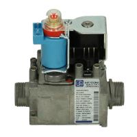
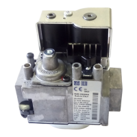
DESCRIPTION OF THE VALVE
¿ Control knob
¡ Adjustment knob (versions with manual
gas flow adjustment)
¬ Pilot gas restrictor
√ Thermocouple connection
ƒ Mounting for piezo support
≈ Inlet pressure test point
∆ Outlet pressure test point
« Automatic shut-off valve