REV. 02 20 / 30
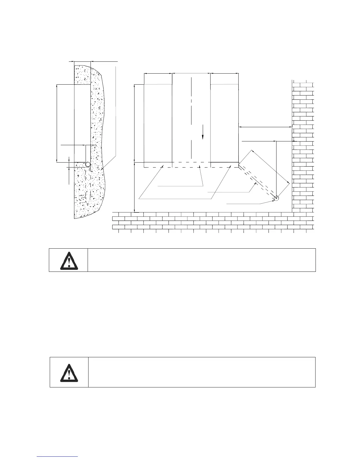
Figure 13 – PIT FOUNDATION PLAN
M
i
n
.
1
2
0
0
m
m
M
a
x
.
1
5
0
0
m
m
Min.400mm
1580mm
Drive up
≥2000mm
To control unit
770mm
580mm
Min.1600mm
580mm
330mm
100
1580mm
Pipe (inner dia.100)
Concrete(Minimum thickness150mm)
Groove 100X100mm
Pipe (inner dia.100)
placed here
100
Specifications of the pit must be adhered to. Failure to do so could cause lift
failure resulting in personal injury or death.
7.5 HYDRAULIC SYSTEM CONNECTION
• Raise platforms at the half way with auxiliary equipment by using strong ropes, bands or
chains.
• Open the front cover of the control unit.
• Referring to the figure 14 route hydraulic lines through the hole in the prepared pit.
• Connect hydraulic hoses to the fittings referring to the letters shown on them.
• Tighten thoroughly.
When routing the hydraulic hoses in the pit, make sure that the hose is clear of
any moving part, make sure to keep the hoses and fittings clean from dust.
Failure to do so may result in hydraulic line failure which may result in
damage or personal harm.