The analog inputs are provided for:
o Pressure transducer
o Temperature switch
o Switch polled in mA or volt, e.g., 4-20 mA,
1-6 volt, etc.
• Connect power supply for analog switch (+)
to plus terminal (+).
• Connect ground connection for analog
switch (-) to minus terminal (-).
• Connect signal line for analog switch to cor-
responding input terminal (I1 /I2).
)see Figures 4/5, item 3, and Fig. 12
X3
Plus
Minus
The digital inputs are provided for:
o Pressure switch
o Proximity switch
o Flow sensor
o Fill level switch
o Interim lubrication switch
• Connect power supply for digital switch (+)
to plus terminal (+).
• Connect ground connection for digital switch
(-) to minus terminal (-).
• Connect signal line for digital switch to cor-
responding input terminal (I3 to I10).
1) No grounding connection (minus) is supported for
two-wire sensor designs (plus + signal).
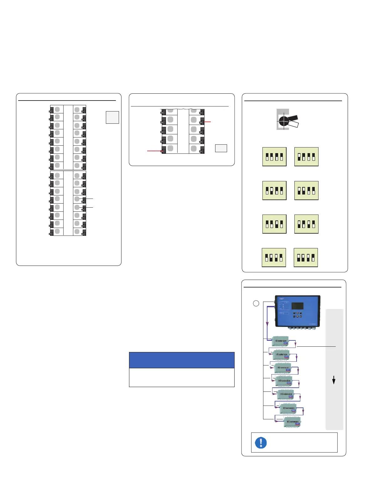
4.8 Adding an additional IO connection to
RS485 interface
)see Figures 4/5, item 8
)see Figures 13/14
ATTENTION!
A separate address must be assigned to each
IO board!
To differentiate between multiple IOPCBs in
an RS485 daisy chain, each IOPCB needs its
own address.
This can be set in the binary code using the
DIP switch (address switch).
If all four DIP switches are set to top, the
address is "1". See Figure 13 for further
addresses.
Another IPCB communication connection can
be established using the two RS485 connec-
tors (5).
Up to 7 IOPCBs can be connected to a
mainboard. Each IOPCB must be supplied
separately.
Set IO addresses, Fig. 13
ON
1 2 3 4
ON
1 2 3 4
ON
1 2 3 4
ON
1 2 3 4
ON
1 2 3 4
ON
1 2 3 4
ON
O
ON
1 2 3 4
ON
1 2 3 4
Address 1 Address 2
Address 3 Address 4
Address 5 Address 6
Address 7 Address 8
Adr. 1
Adr. 2
Adr. 8
Daisy chain with external IO boards, Fig. 14
ATTENTION!
Use shielded cables.
Maximum cable length 200 m.
+
)see Figures 4/5, item 2, and Figure 11
4.7.5 Terminal strip for digital inputs
Terminal strip for digital inputs, Fig. 11
+
I 3
I 4
-
+
I 5
I 6
_
+
I 7
I 8
-
+
I 9
I10
_
I = Input
X2
Plus
Minus
1
)
1) No grounding connection (minus) is
supported for two-wire sensor designs
(plus + signal).

 Loading...


