Quick Setup/Installation Guide for Lubrication Monitor Controller LMC 301
951-150-029-EN
2
Contents
Quick Setup/Installation Guide 1
1. Safety instructions 3
1.1 General safety instructions 3
1.2 General behavior when handling
the product 3
1.3 Qualified technical personnel 3
1.4 Electric shock hazard 3
1.5 Operation 3
1.6 Assembly/maintenance/malfunction/
decommissioning/disposal 4
1.7 Intended use 4
1.8 Foreseeable misuse 4
1.9 Disclaimer of liability 4
1.10 Referenced documents 4
2. Overview 5
3. Technical data 7
3.1 General technical data 7
4. Assembly 8
4.1 Port dimensions, assembly holes,
and minimum mounting dimensions 8
4.2 Open the control unit 8
4.3 Assembly of the control unit 8
4.4 Electrical connection
4.4.1 General 9
4.5 Line routing 9
4.6 Connecting wires 9
4.7 Terminal board 100 to 240 VAC 10
4.7.1 Terminal board 24 VDC 10
4.7.2 Power supply
100 to 240 VAC and 24 VDC 11
4.7.3 Terminal strip for relay outputs 11
4.7.4 Load switching relay 11
4.7.5 Terminal strip for digital inputs 12
4.7.6 Terminal strip for analog capable inputs 12
4.8 Adding an additional IO connection
to RS485 interface 12
5. Configuration by operator/local admin 13
5.1 Configuration of the controller unit
with PC software 13
5.2 Configuration of the controller unit
via the display on the controller unit 13
5.2.1 Status/overview 13
5.2.2 Main menu 13
5.2.3 General setting options 14
5.2.4 Menu structure for system
configuration 15
5.3 Configuration of several IO boards
to master slaves 16
5.3 Menu navigation for operators
without password access 17
5.4 Menu navigation for local admins
with password access 18
6. System configuration 19
Single Line
Menu navigation for system configuration:
6.1 Single Line pump settings with
Supervisor password 19
6.2 Single Line zone settings 20
Progressive
Menu navigation for system configuration:
6.3 Progressive pump settings with
Supervisor password 21
6.4 Progressive zone settings 22
Dual Line
Menu navigation for system configuration:
6.5 Dual Line settings with Supervisor
password 23
6.6 Dual Line Zone control
6.6.1 with two 3/2 solenoid valves or
with EMU 2 24
6.6.2 with EMU 3 25
6.6.3 with DU1 26
6.6.4 with MA/MP 27
Information symbols within the text
Symbol Meaning
Prompts an action
o
Used for itemizing
Refers to other facts, causes,
or consequences
Provides additional informa-
tion within procedures
Abbreviation Designation
DI
Digital Input
AI
Analog Input
DO
Digital Output
AO
Analog Output
BA
Operating instructions
LMC 301 for:
Single Line lubrication system
Document No.
951-180-067-EN
Progressive system
Document No.
951-180-068-EN
Dual Line system
Document No.
951-180-069-EN
M
Software manual for
LMC 301 PC Software
Single Line lubrication system
Document No.
404679A
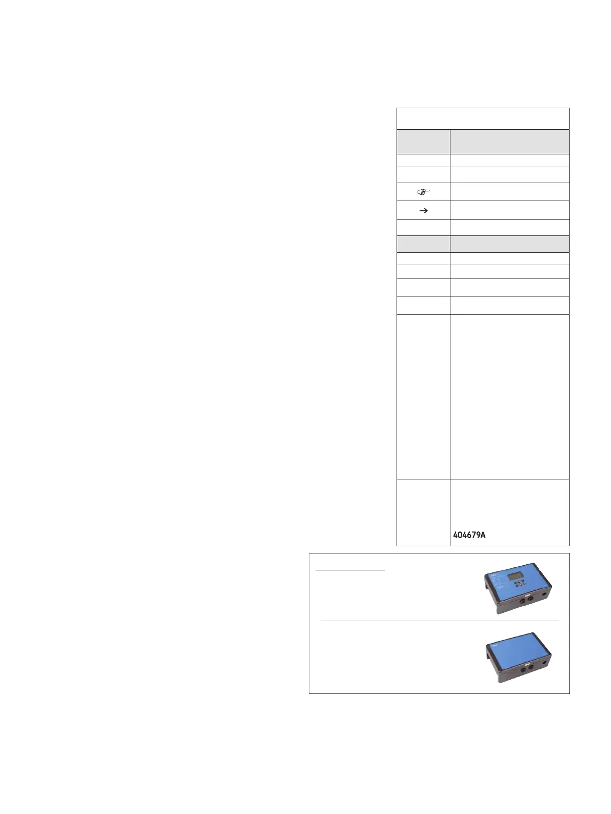
LMC 301 Versions
Master Order Number
24 VDC 086500
100 to 240 VAC 086501
Slave Order Number
24 VDC I/O 086502
100 to 240 VAC I/O 086503
 Loading...


