Technical Instructions Comfodesk Foot Switch STF/STH/STG
531d2950_03/01 Magnetic – The Linear Drives Company™ Page 3/6
3 Installation and commissioning
3.1 Components supplied
The foot switch comprises
1 to 5 pushbutton pairs, with connected cable set.
Options
Expanding threaded inserts (ZBE-521122)
Rubber stops (ZBE-135310)
3.2 Installation
Free-standing installation with rubber stops
The foot switch can be positioned on any level surface using the 4 rubber stops (see
options).
Fixed installation
For fixed installation there are 4 holes with embedded expanding threaded inserts.
See fig. 1:
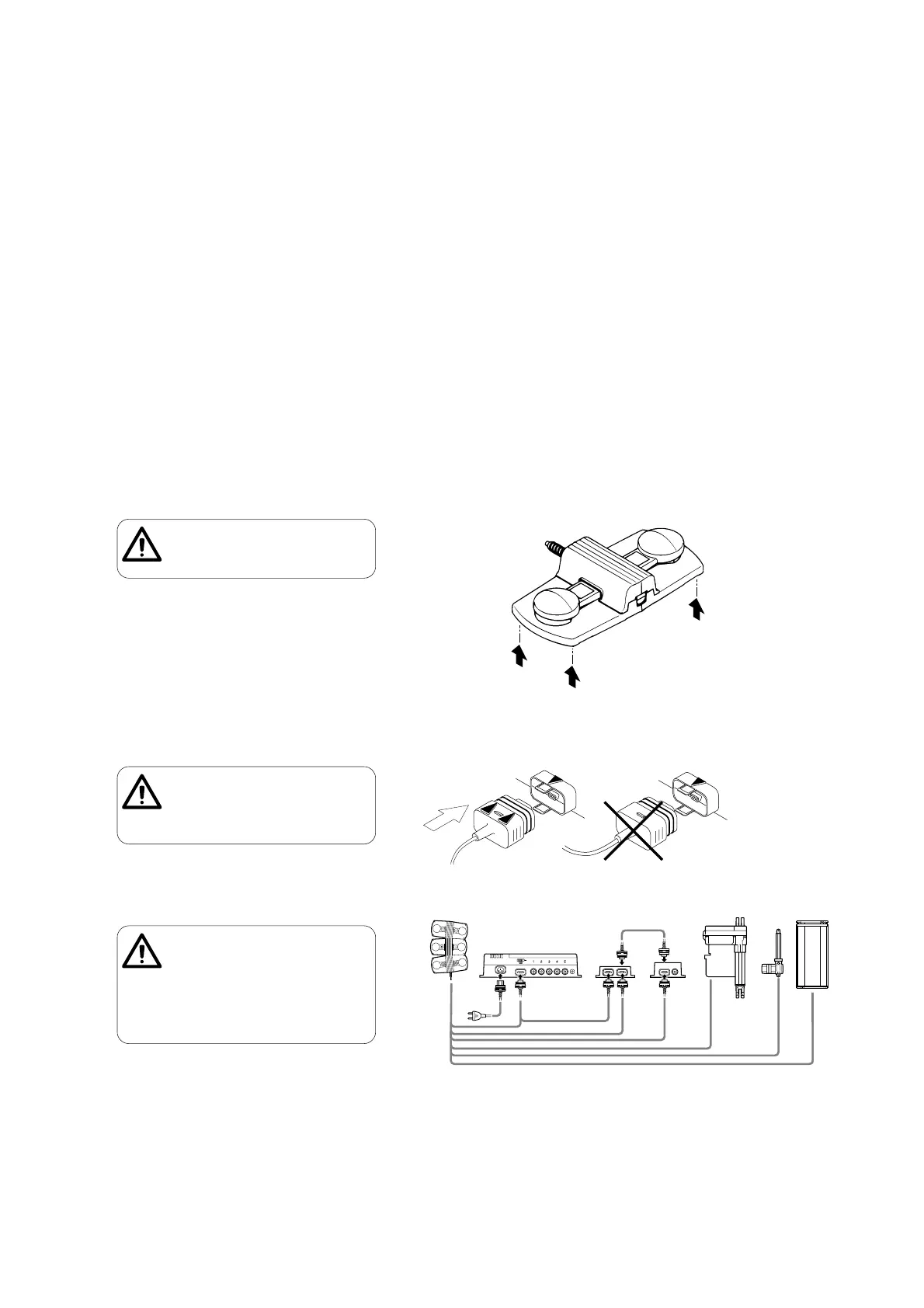
3.3 Connection
The foot switch line is connected to the relevant control unit, the blocking device
(SPP), the distribution box (ZVB) or directly to the drive.
Fig. 3 shows various connection options:
When connecting the foot switch to the relevant equipment, please observe the
technical instructions for that equipment.
Fig. 1 – Installation
Fig. 2 – Insert plugs correctly
Ensure that the entire surface of the switch
is locating correctly, otherwise operation
may be impaired.
Ensure that the plug is inserted into the
correct socket, otherwise there may be a risk
of the socket in the equipment being
destroyed. Note the plug shape (arrows must
be at the top).
Fig. 3 – Connection options
All cables must be secured so that no forces
are exerted on the plug connections on the
foot switch.
Stripped plugs and cables may destroy the
foot switch!
Cables must not be bent or clamped in any
way. This may cause malfunctions due to a
short circuit.
 Loading...