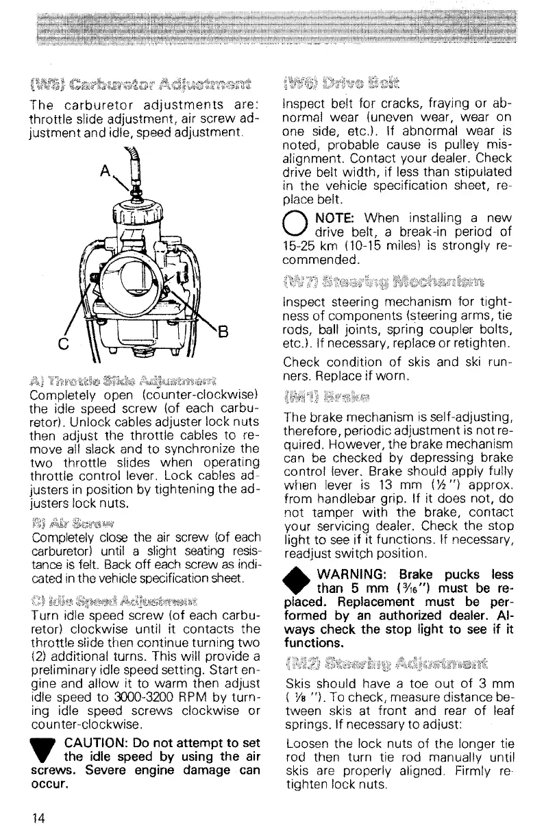
The
carbureto
r
adjustments
are:
throttle
slide adjustment, air
screw
ad-
justment
and idle, speed adjustment.
B
Inspect belt
for
cracks, fraying or ab-
normal wear (uneven wear, wear on
one side,
etc.J.
If abnormal wear is
noted, probable cause is pulley mis-
alignment. Contact your dealer. Check
drive belt
width,
if less than stipulated
in the vehicle specification sheet, re-
place belt.
a
NOTE:
When
installing a
new
drive belt, a break-in period of
15-25 km
(10-15
miles) is strongly re-
commended.
Inspect steering mechanism
for
tight-
ness
of
components (steering arms, tie
rods, ball joints/ spring coupler bolts/
etc.). If necessary, replace or retighten.
Check condition of skis and ski run-
ners. Replace
if wo rn.
Completely open {counter-clockwise}
the idle speed
screw
(of each carbu-
retor). Unlock cables adjuster lock nuts
then adjust the
throttle
cables to re-
move
all slack and to synch ronize the
two
throttle
slides
when
operating
throttle control lever. Lock cables ad-
justers in position
by tightening the ad-
justers lock nuts.
Completely close the air screw
(of each
carburetor) until a slight seating
resis-
tance is felt. Back
off
each screw as indi-
cated
inthe vehiclespecification sheet.
Turn idle speed screw (of each carbu-
retor) clockwise
until it contacts the
throttle slide then continue turning
two
(2) additional turns. This will provide a
preliminary idle speed setting. Start en-
gine and
allow
it to
warm
then adjust
idle speed to
3000-3200
RPM by
turn-
ing idle speed screws clockwise or
counter-clockwise.
..
CAUTION: Do
not
attempt
to
set
...
the idle speed by using the air
screws. Severe engine damage can
occur.
14
The brake mechanism is self-adjusting,
therefore
1 periodic adjustment is
not
re-
quired. However, the brake mechanism
can be checked by depressing brake
control lever. Brake should apply fully
when
lever is 13 mm
(~")
approx.
from
handlebar grip. If it does not, do
not
tamper
with
the
brake,
contact
your servicing dealer. Check the stop
light to see if it functions. If necessary,
readjust
switch position.
.....
WARNING:
Brake pucks less
....
than 5 mm
(=}t1a")
must
be re-
placed. Replacement
must be per-
formed
by an authorized dealer.
Al-
ways check
the
stop
light
to
see if it
functions.
Skis should have a toe
out
of
3 mm
(
Vs
"l, To check, measure distance be-
tween skis at
front
and rear of leaf
springs. If necessary
to
adiust:
Loosen the lock nuts of the longer tie
rod then turn tie rod manually until
skis are properly aligned. Firmly
re,
tighten lock nuts.