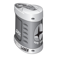
8
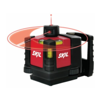
- slide switch F to position 5 (indicator E lights up green)
- if the automatic levelling function is not possible, e.g. because the surface on
which the measuring tool stands deviates by more than 4° from the horizontal
plane, the laser lines ash and indicator E lights up red
- if this is the case, set up the measuring tool in a level position and wait for the
self-levelling to take place
- as soon as the measuring tool is once again within the self-levelling range of
±4°, the laser lines light up continuously and indicator E lights up green
- when not within the self-levelling range of ±4°, working with automatic levelling
is not possible, because it cannot be assured that the laser lines run at a right
angle to each other
- in case of ground vibrations or position changes during operation, the
measuring tool is automatically levelled in again
- to avoid errors, check the position of the horizontal and vertical laser line with
regard to the reference points upon re-levelling
• Working without automatic levelling
- slide switch F in position 6 (indicator E lights up red)
- when automatic levelling is switched o, you can hold the measuring tool freely
in your hand or place it on an inclined surface
- the laser lines no longer necessarily run vertical to each other
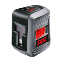
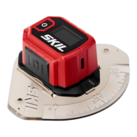
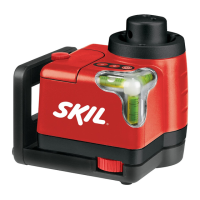
• Attaching with the holder
- with holder G you can fasten the measuring tool to dierent objects ranging in
thickness between 10 and 60 mm, such as vertical or horizontal boards or pipes
- loosen fastening screw H, mount the holder to the desired location and tighten
the fastening screw again
- place the measuring tool via tripod mount J onto the 1/4” male thread K of the
holder and screw it on applying moderate force
! do not overtighten the measuring tool, otherwise it can become
damaged
- adjust the holder roughly before switching on the measuring tool; for this, loosen
locking screw L, move the measuring tool until horizontally positioned at the
desired height and retighten the locking screw
APPLICATION ADVICE
• Always use the centre of the laser line for marking (the width of the laser line
changes with the distance)
• Laser viewing glasses 1 (not standard included)
- laser viewing glasses M 1 lter out the ambient light
- this makes the red light of the laser appear brighter for the eyes
- do not use the laser viewing glasses as safety goggles (the laser viewing
glasses are used for improved visualisation of the laser beam, but they do not
protect against laser radiation)
- do not use the laser viewing glasses as sun glasses or in traffic (the laser
viewing glasses do not aord complete UV protection and reduce colour
perception)
• Working with the tripod (not standard included)
- tripod N 1 oers a stable, height-adjustable measuring support
- place the measuring tool via tripod mount J onto the 1/4” male thread of the
tripod and screw the locking screw of the tripod tight
MAINTENANCE / SERVICE
• This tool is not intended for professional use
• Protect the measuring tool against moisture and direct sun light