,.
.
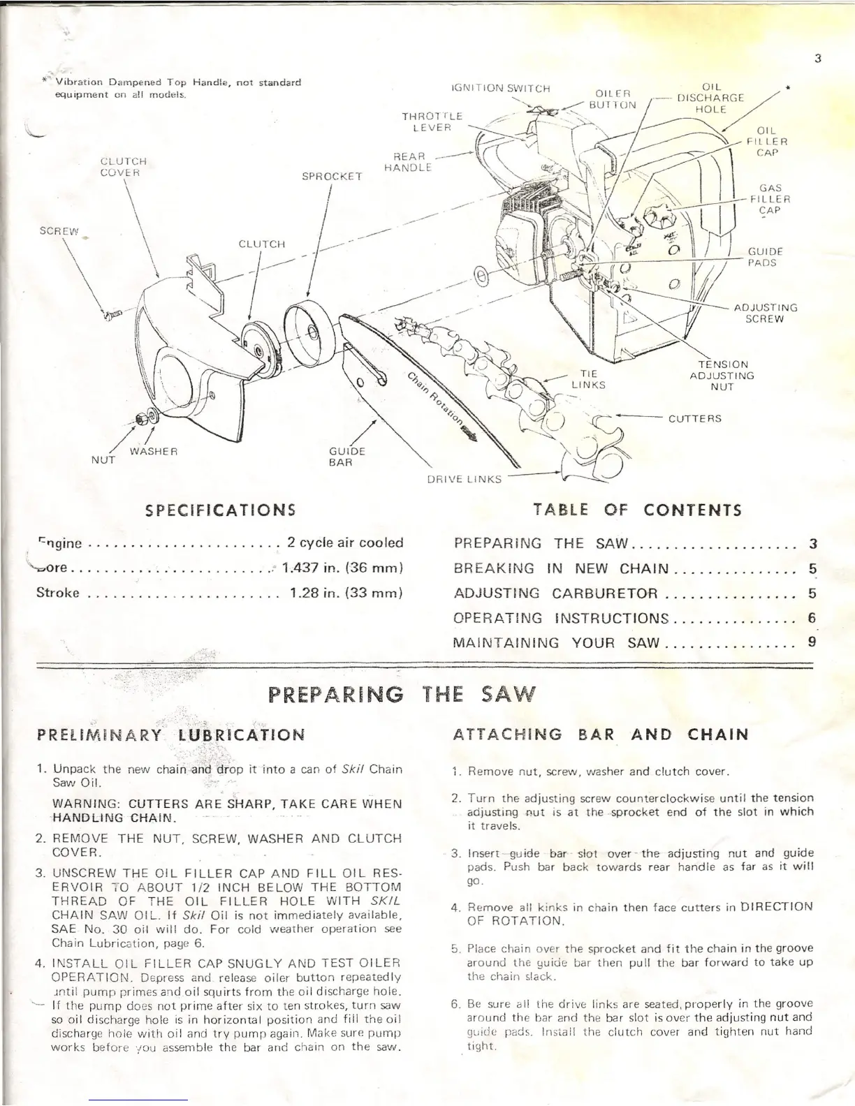
"", Vibration Dampened Top
Handle,
not standard
equ
iprne nt
on
a!1
models.
SPROCKET
I
SCREVI/
/
GUIDE
BAR
SPECIFICATIONS
'=I')gine ,
2
cycle air cooled
are ' 1.437
in.
(36 mm)
Stroke. , 1.28 in. (33 mm)
3
TENSION
ADJUSTING
NUT
CUTTERS
DRIVE LINKS
TABLE OF CONTENTS
PREPARING THE SAW 3
BREAKING IN NEW CHAIN 5
ADJUSTING CARBURETOR................ 5
OPERATING INSTRUCTIONS 6
MAINTAINING YOUR SAW 9
PREPARING THE SAW
PRELIMiNARY'
t'tJ~R;ICAtION
•...
-,
~
-:
1. Unpack the new chain .an~/~;op it into a can of
Ski!
Chain
Saw Oil.
WARNING: CUTTERS ARE SHARP, TAKE CARE WHEN
·HANDUNGCHAIN.
2.
REMOVE THE NUT, SCREW, WASHER AND CLUTCH
COVER.
3.
UNSCREW THE OIL FILLER CAP AND FILL OIL RES·
ERVOIR
-;-0
ABOUT
1i2
INCH BELOW THE BOTTOM
THREAD OF THE OIL FILLER HOLE WITH
SKIL
CHAIN SAW
01
L. If
Ski!
Oil is not immediately available,
SAE No. 30 oil will do. For cold weather operation see
Chain Lubrication, page
6.
4.
INSTALL OIL FILLER CAP SNUGLY AND TEST OILER
OPERATION. Depress and release oiler button repeatedly
.mtil
pump primes and oil squirts from the oil discharge hole.
'- If the pump does not prime after six to ten
strokes,
turn saw
so oil discharge hole is in horizontal position and fill the oil
discharge hole with oil and try pump again. Make sure pump
works before
'IOU
assemble the bar and chain on the saw.
ATTACHING BAR
AND CHAIN
1.
Remove nut, screw, washer and clutch cover.
2.
Turn the adjusting screw counterclockwise until the tension
adjusting Rut is at the .sprocket end of the slot in which
it travels.
3. Insert guide bar slot over- the adjusting nut and guide
pads. Push bar back towards rear hand Ie as far as it wi II
go.
4.
Remove all kinks in chain then face cutters in DIRECTION
OF ROTATION.
5.
Place chain over the sprocket and fit the chain in the groove
around the guide bar then puII the bar forward to take up
the chain slack.
6.
Be sure all the drive links are seated,properly in the groove
around the bar and the bar slot is
over
the adjusting nut and
guide pads. Install the clutch cover
and
tighten nut hand
tight.