17
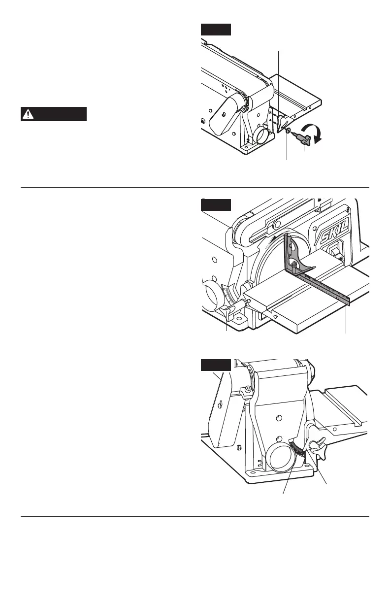
Installing table assembly
(Fig. 4a)
1. Insert the work table index pin into the hole
in the tool’s housing.
2. Position the large at washer over the table
locking knob, then securely tighten the
locking knob by turning it clockwise.
WARNING
To avoid trapping the
workpiece or ngers
between the table and sanding surface, the
table edge should be no more than 1/16”
(1.6 mm) away from sanding surface.
Squaring the work table to the
sanding disc (Fig. 4b & 4c)
1. Using a combination square, check the angle
of the work table with the sanding belt.
2. If the work table is not 90° to the disc, loosen
the table locking knob and tilt the table.
3. Adjust the work table until it is perpendicular
to the sanding disc and retighten the locking
knob.
Note: The bevel pointer should point at 0
on the bevel scale after squaring (Fig. 4c).
If not, contact an Authorized SKIL Service
Station for assistance.
Fig. 4c
Fig. 4a
Index pin
Large at washer
Table locking knob
Tighten
Fig. 4b
Table locking knob Combination square
Bevel scale
Bevel pointer