7/22
3. Connection
The external electric parts of the controller must
only be connected by someone with the proper
electrotechnical qualification. Only connect if the
controller is disconnected from the network
3.1. Assembly
The controller can be installed horizontally or
vertically with the outlets downwards.
It must be mounted on a firm part of the equipment
without direct vibrations.
Drill 4 x 4.2 mm diameter holes with M5 threads into
the base plate on which the controller is mounted.
Fig. 2 shows the spans of the holes. Clamp the
controller with 4 M5 x 8 bolts with fan washers.
Attention! Washers are needed so when tightened
the layer of elox is cut and the controller is
conductively joined to the body of the machine.
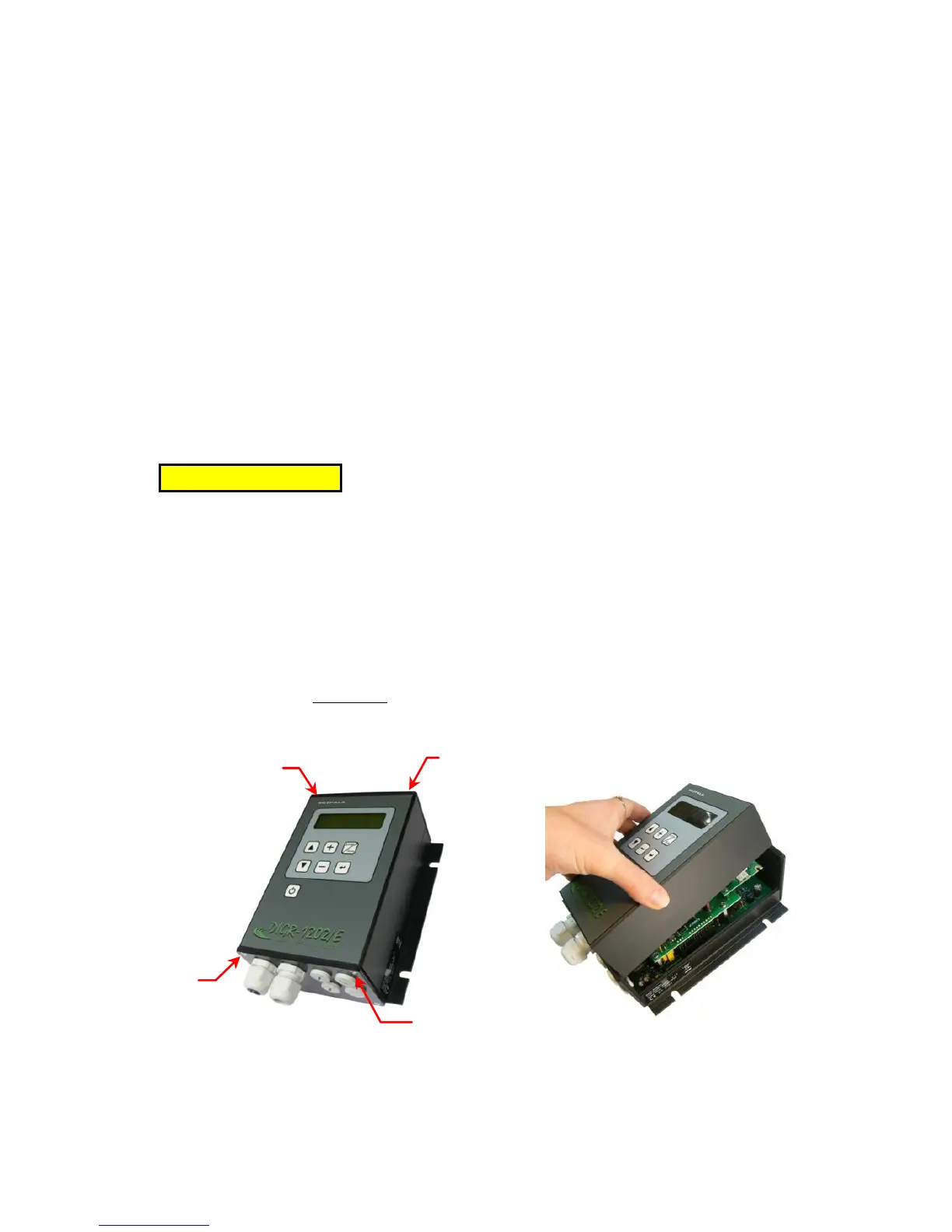
3.2. Dismantling of the cap
Unscrew four bolts M3 fixing the cap of the
controller and remove it (Fig. 4).
Fig. 4 – dismantling of the cap