9/22
Connect according to Fig. 3. If the cable to the coil
is longer than 1.5 m, we recommend connecting with
a shielded cable. The shielding is terminated by the
metal outlet.
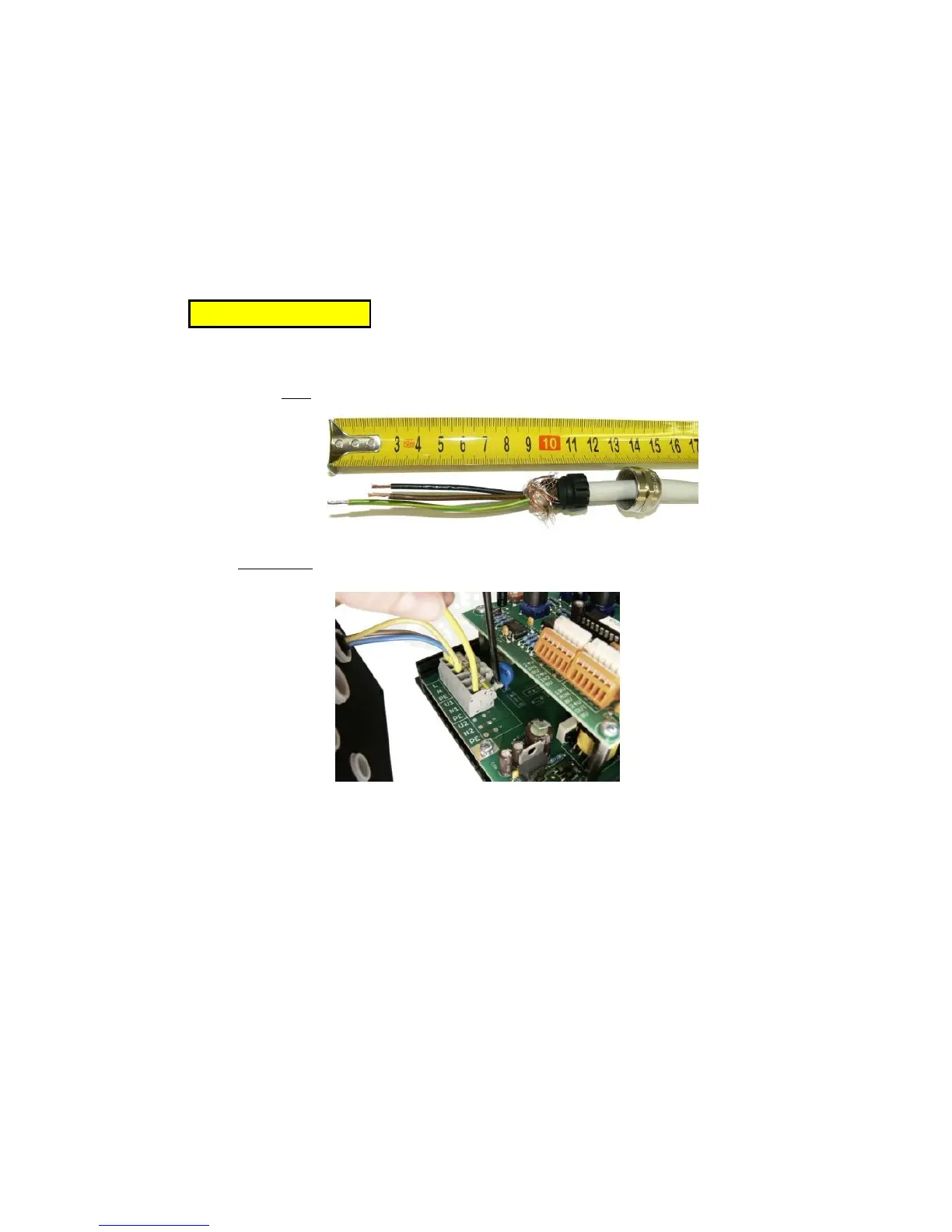
Th termination of power cables is shown in Fig. 7.
The cross-sections of conductors is as follows:
Cross-section of conductors 0.5 - 1.5 mm
2
Cable diameter 8 - 10 mm
Attention! The protective conductor must be at
least 15 mm longer than the other conductors.
Fig. 7 - termination of power cables
Fig. 8 - connecting conductors to terminals
3.4. Connecting the control part
Cross-section of conductors 0.08 - 0.5 mm
2
Diameter of the cable 3 - 6.5 mm
Connect sensors, digital and analogue signals
according to the requirements of the specific
application, according to Fig. 3. Sensors are connected
by a safe separate 24V DC voltage. Use PNP sensors (the
output signal is switched to +24V).
3.5. Re-mounting the cap
After finishing the outside part of controller,
remount the part with outlets and the upper cap. Only
then can the supply voltage be switched on.