10/23
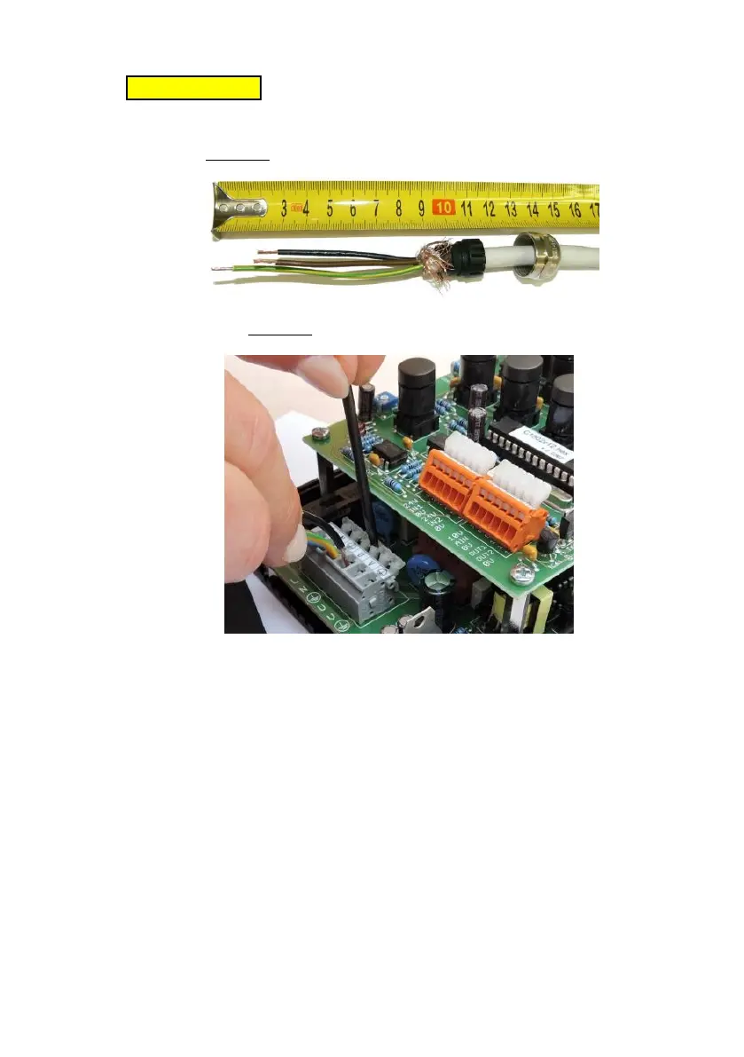
Caution! The protective wire should be at least
by 15 mm longer than the other wires.
Fig. 7 - Termination of power cables
Fig. 8 – Connection of wires
3.4. Connection of the control section
Wire cross section area 0.08 – 0.5 mm
2
Cable diameter 3 - 6.5 mm
Connect the sensors, valves, digital and analogue
signals as required by a specific application, in
accordance with Fig. 3. Detailed explanation - please
see Section 8.7.. The inputs and outputs are fed with
safely separated voltage of 24V DC. Use PNP sensors
(the output signal is switched to +24V).
3.5. Lid reassembly
After completing connection of the external parts of
the controller, carry out reassembly of the part with
grommets and top lid. Only then you can turn power
supply on.