Getting started with the DL850-270
This guide is a compressed version of the
information found in the manuals ‘DL850
Operation and Installation Manual’, and
‘100mm Gate Valve for DL850 Operation and
installation manual’
The diagrams can be found in greater detail in
these manuals.
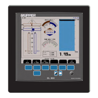
The system comprises of 4 sections:
• The bridge unit
• The transceiver
• The transducer
• Cabling
The Unit is supplied with terminated cable for
the transducer, and yard stock cable can be used
for the longer transceiver – bridge section
(individually screened twisted pair).
Alternatively, this cable can also be provided by
Skipper part nr
ZZK-01011.
Mounting the bridge unit
1. The bridge unit is mounted in or near
the bridge, allowing a space for the air
to escape at the back of the cabinet
(>10mm). The bridge unit will accept
24VDC or 115/230V AC. Power
cables are not provided.
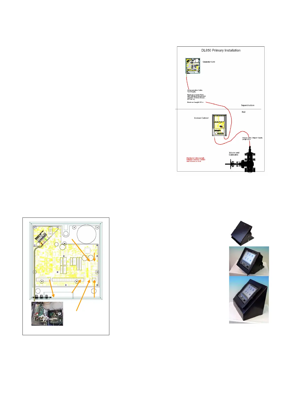
2. Mount the unit using the 3 screws on
the rear (provided) or using the
skipper bracket ordered separately
part nr ZZA-01125 (photo),
alternatively a flush mount bracket
can be ordered ZOA01042. Open the
cabinet, using a Phillips (cross)
screwdriver. Screw the power lines to
the appropriate terminals pt1 or pt 2
(or both). If AC is used, select the correct voltage
using connecter pt 3 or pt 4 (unit supplied in
230V position)
Point 6
Earthing
Point 4
230V
Point 3
115V
Point 1
DC
Point 2
AC
Point 5
switches
3. Ground the unit to ship ground using the grounding terminal (pt 6)