SJIII Compacts & Conventionals
December 2007 Page 17
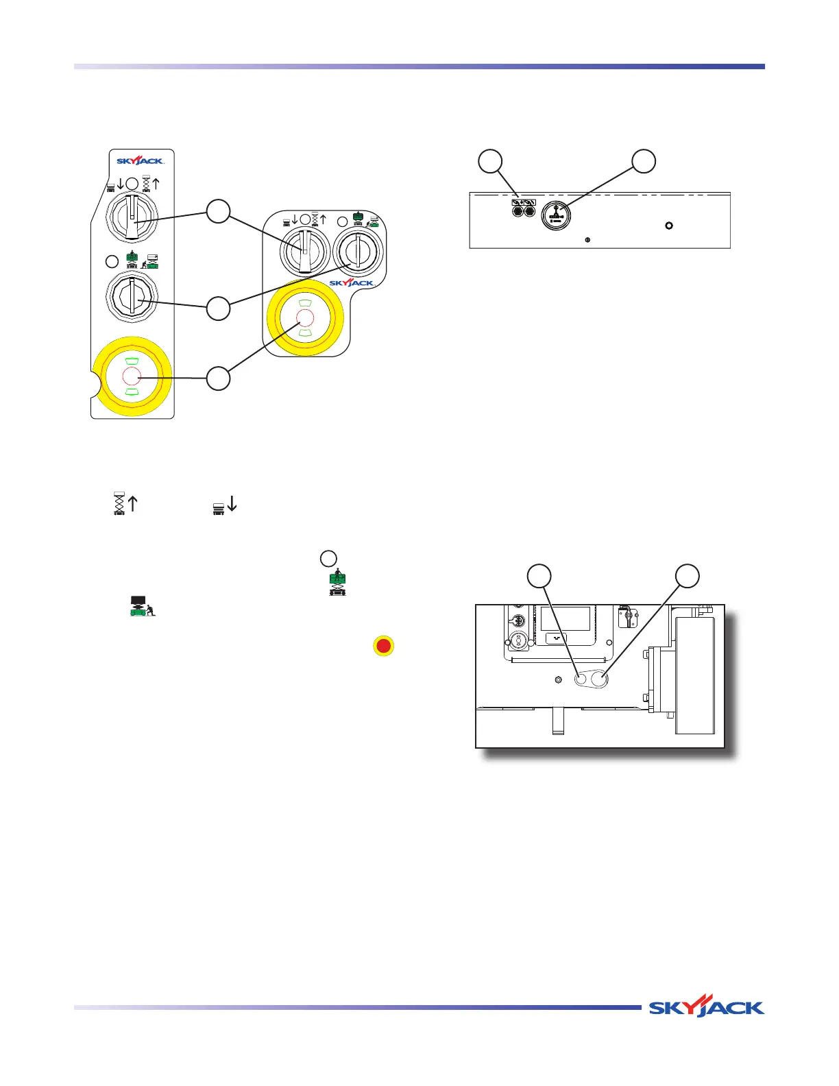
Section 2 - Operation Component Identification
2.5-4 Base Control Console
This control console is located at the rear of the base.
It contains the following controls:
1
2
3
Figure 2-2. Base Control Console
1. Lower/Neutral/Raise Switch - This switch controls
“
” raising or “ ” lowering of platform.
2. Off/Platform/Base Key Switch - This three-way
switch allows the operator to turn “ ” off power
to aerial platform or to activate either “
” platform
or “
” base controls.
3. Emergency Stop Button - This button “
”,
when depressed, disconnects power to the control
circuit.
2.5-5 Electrical Panel
This panel is located in the hydraulic/electric tray. It
contains the following controls:
21
Figure 2-3. Electrical Panel
1. Circuit Breaker Resets - In the event of power
overload or positive circuit grounding, the circuit
breaker pops out. Push the breaker back in to
reset.
2. Hourmeter - This gauge records accumulated
operating time of the aerial platform.
2.5-6 Disc Brake System
The brake system is located at the rear of the base.
The brakes must be manually disengaged before
pushing, winching or towing. Refer to Section 2.14-2
for procedure on how to release brakes manually. The
system contains the following controls:
21
Figure 2-4. Disc Brake System
1. Brake auto reset valve plunger
2. Brake hand pump