Page 12 December 2007
SJRT Compact Series
Engine Powered
Control Functions Section 2 - Familiarization
It is the responsibility of the operator to read, completely understand and follow all instructions and warnings
contained in this operating manual and on the aerial platform.
2.2 Component Identification
The following descriptions are for identification,
explanation and locating purposes only.
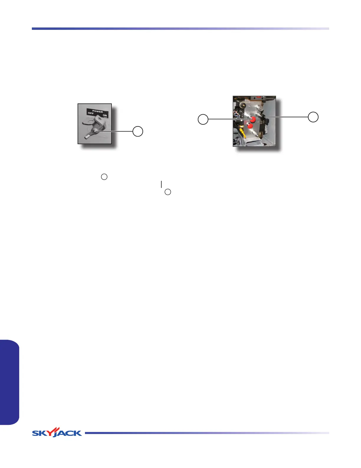
2.2-1 Emergency Main Power Disconnect
Switch
This switch is located at the left side of the engine
compartment.
1
Figure 2-1. Emergency Main Power Disconnect Switch
1. Emergency Main Power Disconnect Switch -
This switch, when in “ ” off position, disconnects
power to all circuits. Switch must be in “ ” on
position to operate any circuit. Turn switch “ ”
off when transporting aerial platform.
2.2-2 Motion Alarm
The alarm produces an audible sound when any control
function is selected. On aerial platforms with certain
options, a flashing amber light will accompany this
alarm.
2.2-3 Tilt Alarm
The aerial platform is equipped with a device which
senses when the aerial platform is out of level in any
direction. When activated, it disables drive and lift
functions of the aerial platform and an alarm produces
an audible sound accompanied by the amber light. If
the alarm sounds, lower the platform completely, then
reposition aerial platform so that it is level before raising
the platform.
NOTE
If the tilt alarm sounds and the platform does
not, or only partially raises, immediately
lower the platform completely and ensure
that the aerial platform is on a firm level
surface.
2.2-4 Brake System
The brake system is located on the main manifold in
the hydraulic/fuel compartment. The brakes must be
manually disengaged before pushing, winching or
towing. Refer to Section 2.5-2 for procedure on how to
release the brakes manually. The system contains the
following controls:
2
1
Figure 2-2. Brake System
1. Brake hand pump
2. Brake auto reset valve plunger
FAMILIARIZATIONFAMILIARIZATION