Do you have a question about the Skyjack SJ3219 and is the answer not in the manual?
Explains DANGER, WARNING, CAUTION, IMPORTANT symbols for safety.
General information about the manual, specifications, and changes.
Details the schedule based on operating environment and inspection points.
Comprehensive checklist for various inspection types with pass/fail criteria.
Details general inspection steps and warnings for MEWP operation.
Explains the standard numbering system for hydraulic hoses with fitting schedules.
Provides torque values for US standard fasteners in dry and lubed conditions.
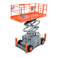
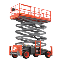
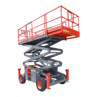
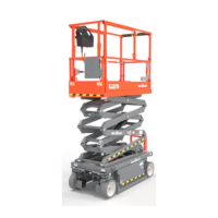
Details technical specifications and features for ANSI/CSA compliant models.
Lists maximum platform capacities for different models and wind ratings.
Defines common electrical symbols used in schematics.
Defines common hydraulic symbols used in schematics.
Lists hydraulic components with their Skyjack part numbers and descriptions.
Lists electrical components with their Skyjack part numbers and descriptions.
Hydraulic schematic diagram specific to SJ3215 ANSI/CSA models.
Electrical schematic diagram for ANSI/CSA compliant models.
Explains the structure of the troubleshooting section and how to use it.
Troubleshooting steps for electrical system issues.
Addresses scenarios where all controls are unresponsive, listing probable causes and remedies.
Troubleshooting guide for hydraulic system malfunctions.
General information to assist in using the procedures in this chapter.
Emphasizes safety and proper practices during maintenance.
Covers procedures related to the MEWP platform.
Covers procedures related to the MEWP base.
Provides procedures for servicing and charging the MEWP battery.
Explains charger maintenance, indicator lights, and troubleshooting.
Introduces the Skycoded Control Module (CM1) and its functions.
Explains key functions for calibration and diagnostics using the Skycoded display.
Explains how the display shows machine conditions, help messages, and flash codes.
Procedure for placing the CM1 module into override mode for servicing.
Steps for initial setup and changing defaults after replacing the CM1 module.
Explains how to access different levels of the CM1 module for settings and calibrations.
Procedure to calibrate the CM1 module's integral tilt sensor for accurate leveling.
Step-by-step guide to calibrate the CM1 module for platform load sensing.
Instructions for changing the language displayed on the Skycoded panel.
Lists fault codes encountered during calibration and their descriptions.
| Gradeability | 25% |
|---|---|
| Power Source | Electric |
| Drive Motor | 24V DC |
| Tire Type | Solid, non-marking |
| Lift Capacity | 550 lbs |
| Machine Width | 32 in |
| Machine Length | 70 in |
| Drive Speed (Stowed) | 2 mph |
| Drive Speed (Raised) | 0.8 km/h |
| Turning Radius (Inside) | 0 in (0 m) |
| Battery | 4 x 6V |
| Working Height | 25 ft |