123
Section 5 – Procedures Skycoded Module
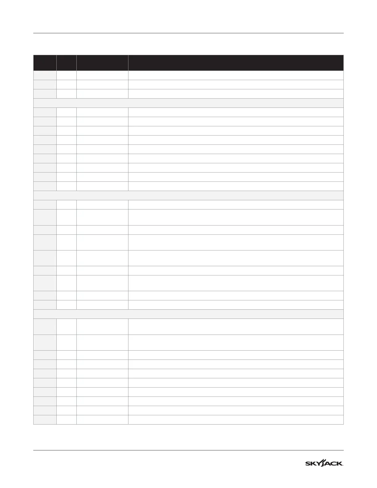
Skycoded Control Module Pin Chart
PLUG
PIN
#
WIRE # AND
COLOUR
PIN OUT
B+ 03B Black Lug for 24V supply voltage (from C1 Motor Contactor relay N.O. contact)
B- 00 Black Lug for 0V reference from Battery negative (negative bus bar)
M M- Black Lug for Output of Pulsed Negative (-) to initialize Pump Motor
Outputs and Analog Inputs
P1 1 08B Green 5V supply to Joystick PCB P8
P1 2 59 Orange/Black 0-5V Proportional Input from Joystick Analog PCB Output P7
P1 3 00B White/Black 0V reference to Joystick PCB P6
P1 4 19D White/Red Input for Shutdown signal from Elevate Trackunit Telematics option (if equipped)
P1 5 CAN H Communication CANbus High (if equipped)
P1 6 CAN L Communication CANbus Low (if equipped)
P1 7 Not Used Not Used
P1 8 60 Red/White 0V Reference Output (pulsed) for PL-1 Overload Light & PL-2 Overload Light
P1 9 29 Blue/Yellow 0V Reference Output (pulsed) for BP-29 Beeper for All-Motion, Tilt and Overload
Connects to Sensors
P2 1 Not Used Not Used
P2 2 28 Green/Red
0-5V Proportional Input from AT1 Angle Transducer Analog Output signal
(3.7 Volts when stowed)
P2 3 Not Used Not Used
P2 4
60A Black/Red/
Green
0-5V Proportional Input from PT1 Pressure Transducer Analog Output signal
P2 5 28A Green/Red
0-5V Proportional Input from AT1 Angle Transducer Analog Output signal
(3.7 Volts when stowed)
P2 6 Not Used Not Used
P2 7 910 Black
Output supply 24V (B+) for AT1, PT1 Transducers, Pothole Protection Limit switches
LS1, LS2, and Beeper BP-29
P2 8 00C White 0V Reference Output to Holding Solenoids (2H-13-1 & 2H-13-2)
P2 9 22 Orange/Blue 0V Reference Output (pulsed) to FL-22 Flashing Light
Platform Controls
P3 1 08C Purple/White
24V Input from S10 Idle/PLTF/Base Key Switch for Platform and/or Base signal
** required input for any movement **
P3 2 08 Blue/White
24V Input B+ Valve supply IF BOTH Emergency Stops are energized
(supplies all valve outputs) ** required input for any movement from Platform **
P3 3 18 Red/Black 24V Input from S27 Torque Switch for High Torque signal
P3 4 120 Black 24V Input from S17 Indoor Select switch for Indoor signal (if equipped)
P3 5 10 Blue/White 24V Input from S10 Idle/PLFT/Base Key Switch for Base signal
P3 6 12 Blue 24V Input from S3 Lift/Off/Drive Switch for Drive signal
P3 7 09 Orange 24V Input from S3 Lift/Off/Drive Switch for Lift signal
P3 8 23 Black/White 24V Input from S7-2 Joystick PCB P3 Steer Right signal
P3 9 24 Blue/Black 24V Input from S7-3 Joystick PCB P1 Steer Left signal
P3 10 51A White (KC built machines only) 24V Input from Anti-Overrising Limit switches N.O. contacts