Page 42 December 2007
Rough Terrain Scissors
TM
Component Identification (Special Options) Operation - Section 3
3.6 Component Identification
(Optional Equipment/Attachments)
This section describes the components that are optional
to MEWPs.
3.6-1 Outrigger/Generator Control Console
(Auto-leveling) (If Equipped)
The outrigger/generator control console is located
next to the platform control console. These switches
control the generator, and outriggers’ extension and
retraction.
4
1
2
5
3
Figure 3-4. Outrigger/Generator Control Console with
All Options
1. Generator Switch - This switch activates the
generator.
2. Outrigger Extend/Retract Switches - These
switches control the extension or retraction of
each individual outrigger.
3. Auto-level Switch - In the “ ” extend position,
each outrigger extends and automatically adjusts
until MEWP is level. In the “
” retract position,
the outriggers retract.
4. Outrigger Enable Switch - This “ ” outrigger
enable switch, when in the extend or retract
position, activates functions on the auto-level
switch and outrigger extend/retract switches.
5. Leveling Indicator Light - This light illuminates
to display the status of the outriggers when the
auto and manual level functions are in use. The
indicator light has the following states:
Off: The outriggers are fully retracted.
Flashing Rapidly: The outriggers are extending
but the platform is not level.
Flashing: The outriggers are extended but the
platform is not yet level.
Solid: The outriggers are extended and the
platform is level.
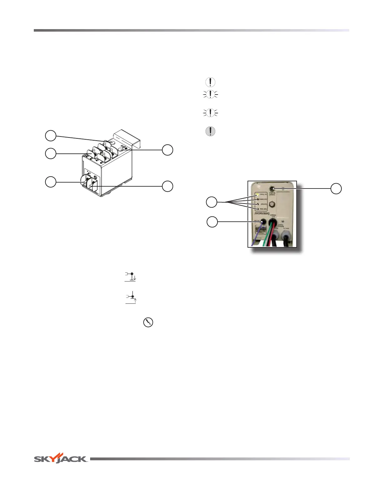
3.6-2 800W AC Inverter (If Equipped)
The inverter is located on the base of the MEWP. It has
the following controls:
1
2
3
Figure 3-5. 800W AC Inverter
NOTE
The inverter operation is automatic. These
controls do not need to be manipulated
for normal operation.
1. Status LEDs - These LEDs indicate the operating
or fault status of the inverter.
2. ON/OFF Wire - This wire is the connection to turn
the inverter on.
3. 15 Amp Circuit Breaker - In the event of a power
overload or circuit grounding, the circuit breaker
pops out. Push the breaker back in to reset.
 Loading...