EasyManua.ls Logo

SkyLink WD-434 - User Manual

SkyLink WD-434
2 pages
Print Icon
To Next Page IconTo Next Page
Loading...
In order for the sensor to communicate with the receiver properly, the
sensor’s code must match with the receiver’s code. Code connectors 1
to 6 can be found by opening the top cover of the sensor and the back
cover of the receiver. User is required to set these code connectors
randomly and the code settings on the sensor and receiver must be the
same. Each position of the code connector can be set to “+”, “-” or “0”
position. Refer to the diagram below to set the code connectors
properly. If the connector is placed on the top and middle posts, that
column is set on “ + ”. If the connector is placed on the middle and bottom
posts, that column is set on “ - ”. If the connector is removed completely,
(not placed on any posts), it is set to “ 0 ”. (see diagram for examples of
how to set a column to the three different positions).
2. SET UP CODE CONNECTORS AND ZONE CONNECTORS
1. CODE CONNECTORS
Code Connectors on Receiver
Each receiver can work with up to 4 different sensors (to represent 4
different zones on the receiver). There are 2 connectors that determine
the zone number 1, 2, 3 and 4. These 2 connectors can be found by
opening the top plastic cover, near the code connectors with marking “A” &
“B”. Please follow table 1 to set the zone.
2. ZONE CONNECTORS
“+” in the table means the connec tor for that position should be placed on
the posts.
“-“ in the table means the connector for that position should be removed.
A B
Zone 1 + +
Zone 2 + -
Zone 3 - +
Zone 4 - -
Note: If you experience interference from a nearby system, which could
accidentally trigger your system, please change the code settings on the
sensor and receiver. The code setting on the sensor and receiver should
still match after changing the code setting.
Table 1
After setting up all the connectors, both units are ready to be powered up.
Plug in the adapter to the receiver, the green LED will start flashing
indicating the receiver unit is powered up but no sensor is detected.
Remove the top cover of the sensor and insert the 3V lithium battery to
the sensor as shown in the diagram.
Plug in the adapter to the receiver
2. SET UP CODE CONNECTORS AND ZONE CONNECTORS (CONT)
‘+’
‘-’
0
Door/Window Alert
Model WD-434
Sensor
The Door/Window Alert is designed to monitor any door or window
within your house. When the monitored window or door is opened, the
receiver will alert you. It will beep and flash.
In this package, you should find a sensor, a magnet, a Household Alert
®
receiver, an adapter, 3V lithium battery, a clip and other mounting
accessories.
Please follow the instructions below to set up the door / window sensor
and the receiver.
3V Lithium
battery
Mounting plate
2 pcs 3.5 x 18 screws
2 pcs 3.5 x 12 screws
Magnet
Household Alert
®
Receiver
Clip
Adapter
Code Connectors on Sensor
Open the top cover
Zone
connectors
Before inserting the battery, keep the magnet away from the sensor.
After inserting the battery to the door / window sensor, the receiver will
beep and flash. If the door / window sensor is set to zone 1, zone 1 red
LED will flash. The beeping and flashing will continue until the magnetic
contact is close to the sensor.
You are now ready to install the sensor and the magnet to a door or
window.
Note: The receiver may not be able to receive the signal from the sensor
properly if they are too close to each other. Move the sensor further from
the receiver to test again.
Insert 3V lithium battery to the sensor
“+” positive
side up
When the magnetic contact is
closed, the receiver will not beep.
When the magnetic contact is broken (open),
the receiver will beep and a LED will flash.
Clip
Note: A connector can be
removed with the clip,
as shown.
1. INTRODUCTION
3. POWER UP THE HOUSEHOLD ALERT
®
RECEIVER AND DOOR/WINDOW SENSOR
Question and Answer IconNeed help?

Do you have a question about the SkyLink WD-434 and is the answer not in the manual?

Summary

1. INTRODUCTION

2. SET UP CODE CONNECTORS AND ZONE CONNECTORS

1. CODE CONNECTORS

Sets sensor/receiver codes for communication using '+' , '-' , '0' positions for proper operation.

2. ZONE CONNECTORS

Configures receiver zones (1-4) using 'A' & 'B' connectors for multiple sensors.

3. POWER UP THE HOUSEHOLD ALERT RECEIVER AND DOORWINDOW SENSOR

4. INSTALLATION

SELECT A MOUNTING LOCATION

Guides mounting sensor/magnet on door/window frame, ensuring alignment and contact for proper function.

5. OPERATION

6. BUZZER VOLUME

7. MUTE

8. LOSS OF SIGNAL INDICATION

9. OTHER HOUSEHOLD ALERT SENSORS

10. WARRANTY

11. CUSTOMER SERVICE

Overview

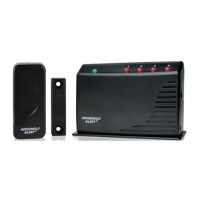
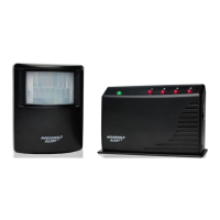
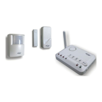
The Door/Window Alert (Model WD-434) is a security device designed to monitor the opening and closing of doors and windows within your home, providing an audible and visual alert when a monitored entry point is breached. This system comprises a sensor, a magnet, a Household Alert® receiver, an adapter, a 3V lithium battery, a clip, and various mounting accessories.

Function Description

The primary function of the Door/Window Alert is to detect when a door or window is opened. When the magnetic contact between the sensor and magnet is broken, the sensor transmits a signal to the Household Alert® receiver. Upon receiving this signal, the receiver will emit an audible beep and flash a corresponding LED light to indicate which zone (and thus which door or window) has been triggered.

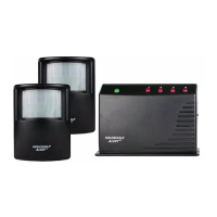
The system supports up to four different zones, meaning a single receiver can monitor up to four separate doors or windows, each assigned a unique zone number (1, 2, 3, or 4). This allows for comprehensive monitoring of multiple entry points from a central receiver unit.

Usage Features

Setup and Configuration: Before operation, the sensor and receiver must be configured. This involves setting up "code connectors" and "zone connectors."

  • Code Connectors: Both the sensor and the receiver have six code connectors that must be set identically for proper communication. These connectors can be set to one of three positions: "+", "-", or "0". The "+" position involves placing the connector on the top and middle posts, the "-" position on the middle and bottom posts, and the "0" position means the connector is removed entirely. This randomizable code setting helps prevent interference from nearby systems that might accidentally trigger your alarm. If such interference occurs, the code settings on both units should be changed to a new matching configuration.
  • Zone Connectors: The receiver has two zone connectors, labeled "A" and "B," which determine the zone number (1, 2, 3, or 4) for each sensor. By placing or removing these connectors according to a provided table, you can assign a specific zone to each sensor. For example, setting both A and B to "+" might correspond to Zone 1.

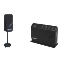
Powering Up: Once the connectors are set, the receiver is powered by plugging in the adapter. A green LED will flash, indicating the receiver is powered but no sensor activity has been detected yet. The sensor is powered by inserting a 3V lithium battery. It's crucial to keep the magnet away from the sensor during battery insertion. After the battery is inserted, the receiver will beep and flash, and the LED for the assigned zone will flash rapidly until the magnetic contact is closed.

Installation: The sensor should be mounted on the door or window frame, and the magnet on the door or window itself. For optimal performance, both components should be mounted as high as possible. A grey alignment marking on one side of the sensor indicates where the magnet should be in contact when the door/window is closed. Mounting can be done using double-sided foam tape for flat surfaces or with the provided mounting plate and screws for added security.

Operation: When the magnetic contact between the sensor and magnet is broken (i.e., the door or window is opened), the sensor sends a signal to the receiver. The receiver will then beep and flash the red LED corresponding to the triggered zone. The pattern of beeps indicates the zone: for example, Zone 1 might produce a continuous "single beep" pattern ("beep, pause, beep, pause..."), while Zone 4 might produce a continuous "4 beeps" pattern ("beep beep beep beep, pause, beep beep beep beep..."). This allows users to quickly identify which entry point has been breached.

Buzzer Volume Control: The receiver features a volume switch that allows users to select between "HI" (high) and "LO" (low) buzzer volumes. The buzzer can also be completely disabled by switching it to the "OFF" position.

Mute Function: If a sensor is triggered for an extended period, the buzzer can be temporarily silenced by pressing the "Mute" button. This will disable the buzzer for all currently activated sensors. However, if another signal is received from any sensor, the receiver will resume beeping. This feature is useful in situations where a door or window might be intentionally left open for a period, such as during cleaning, and you wish to temporarily silence the alarm without disarming the system.

Maintenance Features

Battery Replacement: The sensor is powered by a 3V lithium battery. If the receiver indicates a "loss of signal" for a specific zone, and relocating the sensor closer to the receiver does not resolve the issue, it is likely that the sensor's battery needs to be replaced. The receiver will show a "loss of signal" by rapidly flashing the red LED for the affected zone.

Troubleshooting Signal Loss: If the receiver indicates a "loss of signal" (rapidly flashing red LED for a zone), first try moving the receiver closer to the corresponding sensor and trigger that sensor. If the rapid flashing stops, it means the receiver or sensor needs to be relocated to a position where they can communicate effectively. If the issue persists, replacing the sensor's battery is the next step.

Interference Management: In the event of accidental triggers due to interference from nearby systems, the code settings on both the sensor and receiver should be changed to a new, matching configuration. This helps ensure reliable operation by preventing false alarms.

Optimal Placement: It is noted that the receiver may not properly receive signals from the sensor if they are too close to each other. If this occurs, the sensor should be moved further from the receiver to test for proper communication.

The Door/Window Alert system is designed for ease of use and provides a straightforward method for enhancing home security by monitoring entry points. Its customizable settings, clear alert system, and basic maintenance features make it a practical addition to any household.

SkyLink WD-434 Specifications

General IconGeneral
TypeWireless Door/Window Sensor
ModulationASK
Power Source3V CR2032 lithium battery
Frequency Range433.92 MHz
Operating Voltage3V

Related product manuals