5 - 26
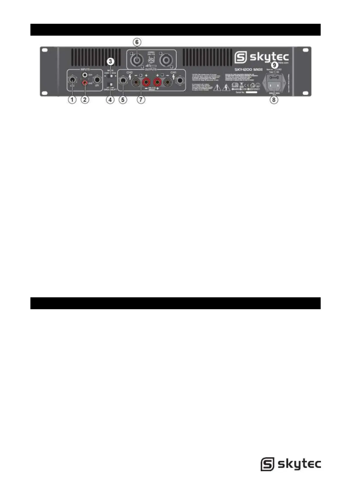
Rear Panel Features
1. 6.3mm Jack inputs.
Two 6.3mm jack female input connector for
connecting a signal source (mixer etc.).
2. RCA inputs.
Two RCA input connector for connecting a
signal source (mixer etc.).
3. Mode Switch.
The amplifier can use 2 different modes:
stereo & bridge.
Choose one of these functions:
Stereo mode: Standard left/right stereo
mode.
Bridge mode: This mode combines both
amps on one channel which results in
double power on this channel. Connects
the signal to the left input channel and the
output level can now be adjusted with the
left volume control.
4. Ground Lift Switch.
Allows circuit and chassis grounds to be
separated in case of problems with earth
loops (hum)..
5. 6.3mm Jack Outputs.
Maximum load in stereo mode 4 Ohm per
channel.
6. Speaker Outputs NL4.
Maximum load in stereo mode 4 Ohm per
channel.
Pin +1 & +2 = + output, Pin -1 & -2 = -
output
7. Binding Post Output Jacks.
Maximum load in stereo mode 4 Ohm per
channel. Maximum load in bridge mode 8
Ohm.
8. Mains Power Connector
9. Fuse
This main fuse secures the amplifier and
wires against defects. Replace this only
with a fuse of same type and value.
Installation
Connecting Output
Make sure the amplifier is turned off before you wire the system. Speakers can be connected using
speaker NL4 plugs or bare wire for your binding post output connectors. Using the guidelines below
select the appropriate size of wire bases on the disctance between the amplifier and speaker.
Distance Wire Size
<10m 1.5mm2
>10m <20m 2.5mm2
>20m <30m 4.0mm2
 Loading...