CP (CHILDPROOF) FEATURE
This remote control includes a childproof feature that allows the user to “lock-out” operations from the Transmitter.
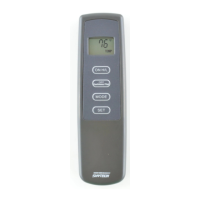
To activate and de-activate the childproof feature, press and hold the • ON button and the TIMER button at the same time for 5 sec-
onds. The letters “CP” will appear in the TEMP frame on the LCD screen when childproof mode is activated.
“CP” will appear on the LCD screen if any button is pressed while childproof mode is engaged.•
When this mode is engaged, all auto settings go on without interruption (like thermostat). Only manual functions are prevented.•
REV 4/15/11 Page 3
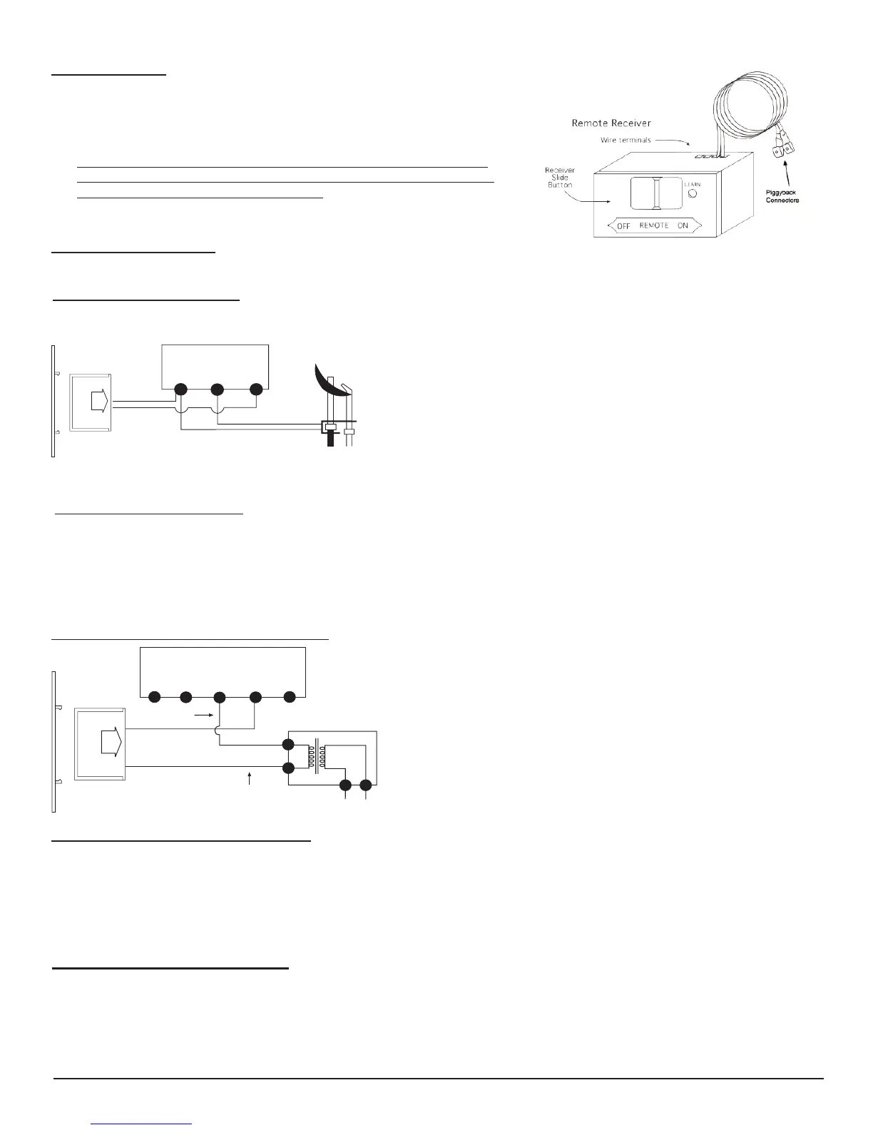
WIRING INSTRUCTIONS
Aqualiedelectricianshouldinstalltheremotecontrolsystem.
TERMINAL BLOCK
ON MILLIVOLT
GAS VALVES
TH
TP
TP
TH
THERMOPILE/
PILOT LIGHT
REMOTE
RECEIVER
Connect one wire from the remote receiver to the TH terminal on the gas •
valve.
Connect the other wire from the remote receiver to the TH/TP terminal on •
the gas valve.
WIRING MILLIVOLT VALVES
MILLIVOLT SYSTEM CHECK
Ensurethatthepilotameislit.•
Slide the 3-position button on the remote receiver to the • ONposition.Themaingasame(i.e.,there)
should ignite.
Slide the button to • OFF.Themainameshouldextinguish(thepilotamewillremainon).
Slide the button to • REMOTE, then press the ON button on the transmitter to change the system to on. The main
gasameshouldignite.
ELECTRONIC SPARK SYSTEM CHECK
Slide the 3-position button on the remote receiver to the • ON position. The spark electrode should begin sparking to ignite the pilot.
Afterthepilotameislit,themaingasvalveshouldopenandthemaingasameshouldignite.
Slide the button to • OFF.Themaingasameandpilotameshouldbothextinguish.
Slide the button to • REMOTE, then press the ON button on the transmitter to change the system to on. The spark electrode should
beginsparkingtoignitethepilot.Afterthepilotislit,themaingasvalveshouldopenandthemaingasameshouldignite.
WIRING ELECTRONIC SPARK IGNITIONS
ELECTRONIC MODULE
TR
TH
REMOTE
RECEIVER
neutral wire
24VAC
hot wire
120VAC
110/24VAC
Transformer
The remote control receiver can be connected, in series, to a 24VAC
transformer to the TR (transformer) terminal on the ELECTRONIC
MODULE. Connect the hot wire from the 24VAC transformer to either
of the wire terminals on the remote receiver. Connect another wire be-
tween the other receiver wire terminal and the TH (thermostat) terminal
on the ELECTRONIC MODULE.
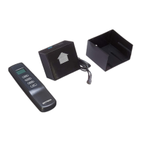
HEARTH MOUNT
Theremotereceivercanbeplacedonthereplacehearthorunderthere-•
place behind the control access panel.
Use the wires attached to the remote receiver to connect to the gas valve or •
the electric module (piggyback connectors have both male & female terminals
forexibility).
Be sure that the connectors do not touch each other or other bare metal •
surfaces; this will cause the appliance to turn on. The connectors may be
wrapped with electrical tape to prevent this.
Skytech 1001T/LCD-A
Toll-Free 1-866-667-8454
NorthlineExpress.com
www.NorthlineExpress.com
Toll-Free 1-866-667-8454
NorthlineExpress.com
www.NorthlineExpress.com