COMMUNICATION - SAFETY - TRANSMITTER - (C/S - T/X)
This remote control has a COMMUNICATION –SAFETY function built into its software to ensure the transmitter and receiver are com-
municating normally.
In all operating modes, the transmitter sends an RF signal every fteen minutes to the receiver indicating that the transmitter is within
the normal operating range of 20 feet. Should the receiver NOT receive this signal, the RECEIVER will begin a 2 hour countdown. If
the RECEIVER does not receive a signal from the transmitter in 2 hours, the RECEIVER will shut off the appliance. The RECEIVER
will then emit a series of rapid “beeps” for a period of 10 seconds. Then after 10 seconds of rapid beeping, the RECEIVER will continue
to emit a single “beep” every 4 seconds until a transmitter ON, OFF or MODE Button is pressed to reset the receiver.
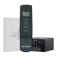
LEARNING TRANSMITTER TO RECEIVER
Each transmitter uses a unique security code. It will be necessary to press the LEARN button on the receiver to accept the trans-•
mitter security code upon initial use, if batteries are replaced, or if a replacement transmitter is purchased from your dealer or the
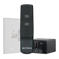
factory. In order for the receiver to accept the transmitter security code, be sure the slide button on the receiver is in the REMOTE
position; the receiver will not LEARN if the slide switch is in the ON or OFF position. The LEARN button in located on the front face
of the receiver; inside the small hole labeled LEARN. Using a small screwdriver or end of a paperclip gently press and release
the black LEARN button inside the hole. When you release the LEARN button the receiver will emit an audible “beep”. After the
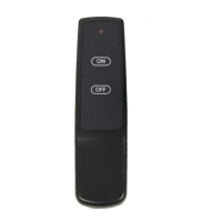
receiver emits the beep press the transmitter ON button and release. The receiver will emit several beeps indicating that the trans-
mitter’s code has been accepted into the receiver.
To delete all of the transmitter codes on your receiver, press and hold the • LEARN button for 10 seconds. Then you will hear a
series of beeps, indicating that the receiver’s memory has been cleared.
TROUBLE SHOOTING
If you encounter problems with your replace system, the problem may be with either the replace itself or with the remote. Review the
replace manufacturer’s operation manual to make sure all connections are properly made. Then check the operation of the remote in
the following manner:
Make sure there is a 110 - volt power source to the transmitter.•
Check batteries in transmitter to make sure contacts are touching (+) and (-) ends of battery. Bend metal contacts in for tighter t.•
Check if the transmitter batteries are fully charged.•
Be sure receiver and transmitter are within 20’-25’ operating range.•
Keep receiver from temperatures exceeding 130 degrees F. •
If receiver is installed in a tightly enclosed metal surrounding, the operating distance will be shortened.•
Make sure the hand-held transmitter and remote receiver are communicating properly (see LEARNING TRANSMITTER TO RE-•
CEIVER section).
BATTERY LIFE
Life expectancy of the alkaline batteries in the transmitter should be at least 12
months. Check and replace all batteries:
Annually.•
When operating range becomes reduced.•
When transmissions are not received by the remote receiver.•
If the hand held transmitter batteries measure less than 2.5 volts. (Both batteries •
in combination)
FCC REQUIREMENTS
NOTE: THE MANUFACTURER IS NOT RESPONSIBLE FOR ANY RADIO OR TV INTERFER-
ENCE CAUSED BY UNAUTHORIZED MODIFICATIONS TO THIS EQUIPMENT. SUCH MODIFI-
CATIONS COULD VOID THE USER’S AUTHORITY TO OPERATE THE EQUIPMENT.
FOR TECHNICAL SERVICE, CALL: U.S. INQUIRIES
888/672 - 8929 OR 260/459 - 1703
WEB SITE: www.skytechsystem.com
CANADIAN INQUIRIES
877/472 - 3923
MANUFACTURED EXCLUSIVELY FOR SKYTECH II, INC
REV 7/24/12 Page 4
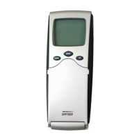
TRANSMITTER WALL CLIP
The transmitter can be hung on a wall using the clip provided.
Wood - Drill 1/8’’ pilot holes and install with screws provided.•
Plaster/Wallboard - Drill 1/4’’ holes, then install with the screws provided.•
WALL CLIP
SLOT
WALL CLIP
BATTERY
COMPARTMENT
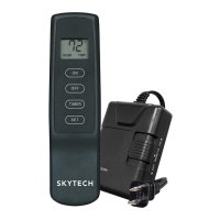
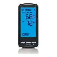
Skytech 1410TH-A
f i r e - p a r t s . c o m
 Loading...