REV 11/27/07 Page 1 of 10
5301
INSTALLATION AND OPERATING INSTRUCTIONS
INTRODUCTION
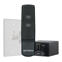
This SKYTECH remote control system was developed to provide a safe, reliable, and user-friendly remote control system for gas heating
appliances. The system can be operated thermostatically or manually from the transmitter. The system operates on radio frequencies (RF)
within a 20’ range using non-directional signals. The system operates one of 1,048,576 security codes that are programmed into the
transmitter at the factory; the remote receiver’s code must be matched to that of the transmitter prior to initial use.
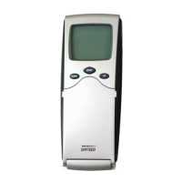
The transmitter operates on 4 AAA-size 1.5V batteries. It is recommended that ALKALINE
batteries always be used for longer battery life and maximum operational performance.
IMPORTANT: New or fully charged batteries are essential for proper operation of the multi-
function transmitter. Insert 4 AAA-size 1.5 V batteries into the battery compartment on the back
of the transmitter, positioning the (+) and (-) ends of the batteries as indicated on the casing.
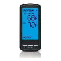
When the batteries are inserted, the screen at right (with
similar numbers) will display.
Note On initial start up if a LOW battery icon appears on
the screen, check the position of the batteries.
Note: Due to the sensitive temperature-monitoring
components in the transmitter, it may be necessary to
allow the transmitter to stabilize to room temperature
before accurate room temperatures are displayed on
the screen. If the transmitter is activated from a
severe cold condition, it can take up to fifteen minutes
for accurate temperature readings to appear.
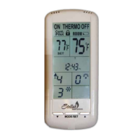
1. BATTERY ICON - Battery power is low. Replace batteries within two weeks.
2. TIMER- Indicates time remaining before system shuts off, when timer-programmed;
9-hour maximum setting.
3. MODE- Indicates operation MODE of system. ON indicates the system is on, either
manually or thermostatically. OFF indicates the entire system is turned off THERMO
indicates the system will automatically cycle on/off, depending on programmed
4. SET- Indicates desire SET room temperature for THERMO operation
5. FLAME – Indicates burner/valve in operation.
6. CLOCK – Indicates the current time in AM/PM
7. ROOM – Indicates CURRENT room temperature.
8.
0
F indicates degrees Fahrenheit (ºC indicates degrees Celsius).
9. LOCK – Child lock out.
OPERATION FUNCTIONS
Note: Touch anyplace on the screen and the screens blue back light will light up
and stay on (5) seconds.
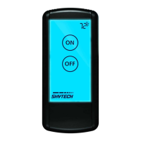
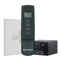
To operate the system, press the MODE/SET
button or press the MODE SECTION on
the LCD screen on the front of the transmitter to select the operational MODE desired.
• ON indicates the system is on, either manually, timed or thermostatically.
• THERMO indicates the system will automatically cycle ON/OFF, depending
• on programmed set temperature.
• OFF indicates the entire system is turned off.
Review COMMUNICATION SAFETY SECTION under TRANSMITTER section and THERMO SAFETY SECTION under REMOTE
RECEIVER section. These signal/temperature safety features shut down the fireplace system when a potentially unsafe condition exists.
IF YOU CANNOT READ OR UNDERSTAND THESE INSTALLATION INSTRUCTIONS DO NOT
ATTEMPT TO INSTALL OR OPERATE
PM
ROOM
SET
TIMER
OFF
OFF
AM
PM
ROOM
SET
TIMER
ON
OFF
ON
OFF
THERMO
AM
LCD DISPLAY SCREEN
1
9
6
3
5
7
2
4
8
MODE/SET
MODE/SET
PM
ROOM
SET
TIMER
OFF
OFF
MODE/SET
BATTERY
COMPARTMENT
BACK
FRONT
PM
ROOM
SET
TIMER
OFF
OFF
AM