Skytech: RCT-MLT-IV
REV. 3-26-19 Page 4
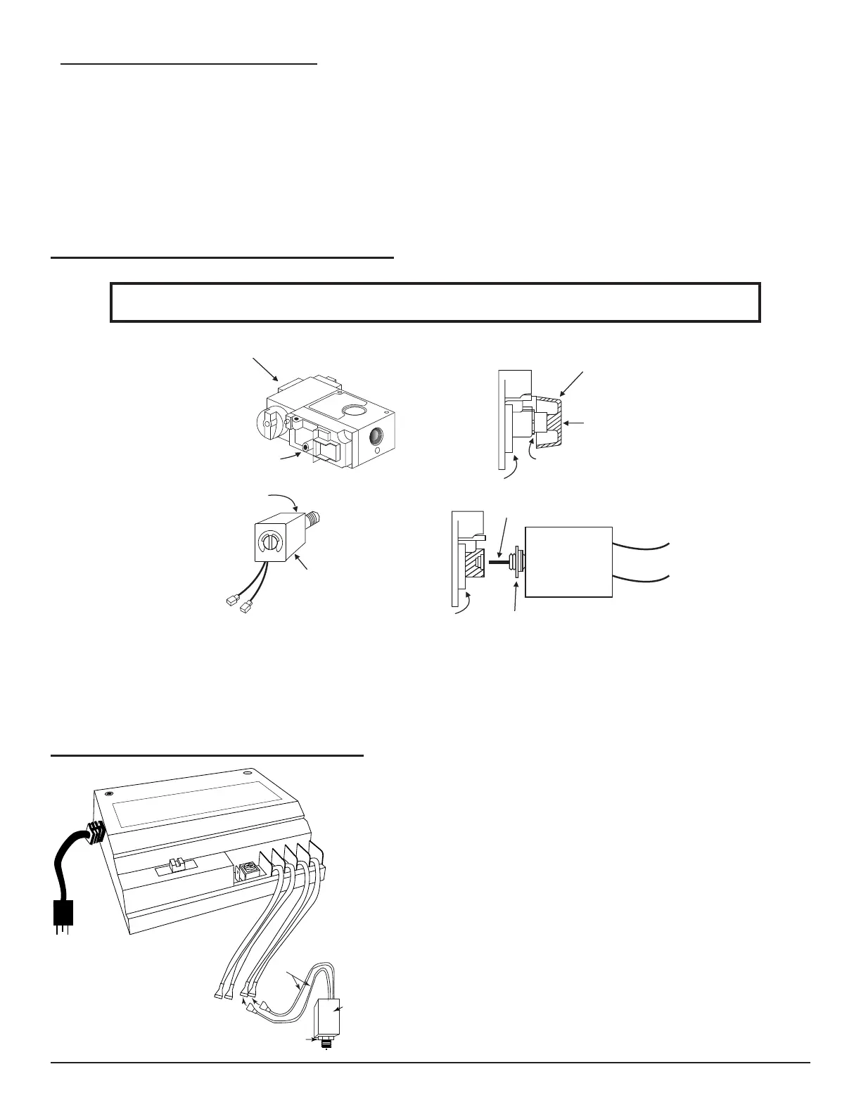
INSTALLING FLAME CONTROL SOLENOID
ALL STEPS REQUIRED FOR INSTALLATION OF THE FLAME CONTROLLER MUST BE DONE BY
A QUALIFIED GAS SERVICE TECHNICIAN
1. Remove the screw and knob from the variable regulator and keep in a safe place.
2. Unscrew the nut from the regulator and keep in a safe place.
3. Remove the bag containing a washer and blue and red plungers from the side of the ame control solenoid.
4. Insert the correct plunger (Blue - natural gas, red - propane) into the ame control solenoid.
5. Thread the ame control solenoid with correct plunger into the thread hole in the variable regulator.
Variable Regulator
Washer
Flame Control
Solenoid
Variable Regulator
Plunger
Jam Nut
Solenoid
Variable Regulator
Nut
Screw
Knob
WIRING SOLENOID TO THE RECEIVER
1. Connect the two leads from the ame control solenoid to the
orange leads from the receiver.
2. Plug the remote receiver into the 110/120 VAC power supply.
3. Light the replace.
4. Tighten the jam nut to the face of the variable regulator body
5. Turn the main gas knob on the gas valve OFF.
CAUTION
TO ENSURE SAFE OPERATION, THE OUTLET PRESSURES
ON BOTH REGULAR AND HI FLAME LEVELS SHOULD BE
CHECKED WITH A MANOMETER IN ACCORDANCE WITH
SPECIFICATIONS SUPPLIED BY THE VALVE
MANUFACTURER.
O
F
F-
R
EMOT
E
-
O
N
G
R
OU
N
D
VA
L
V
E
L
E
AR
N
C
O
N
T
R
O
L
FL
A
M
E
Orange
Wires
Jam Nut
Flame Control
Solenoid
• Slide the 3-position button on the remote receiver to the ON position. The spark electrode should begin sparking to ignite the
pilot. After the pilot ame is lit, the main gas valve should open and the main gas ame should ignite.
• Slide the button to OFF. The main gas ame and pilot ame should both extinguish.
• Slide the button to REMOTE, then select “ON” with the mode button on the transmitter to change the system to on. The spark
electrode should begin sparking to ignite the pilot. After the pilot is lit, the main gas valve should open and the main gas ame
should ignite.
ELECTRONIC SPARK SYSTEM CHECK