Skytech: RCT-MLT-IV
REV. 3-26-19 Page 3
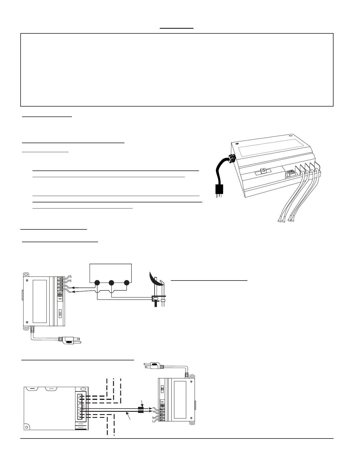
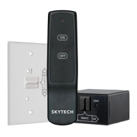
MOUNTING THE REMOTE RECEIVER
HEARTH MOUNT
• The remote receiver can be placed on the replace hearth or under the re-
place behind the control access panel.
• MAKE SURE THAT WHERE THE RECEIVER IS PLACED DOES NOT
EXCEED 170ºF. IT WILL CAUSE DAMAGE TO THE PRODUCT.
• Use the wires attached to the remote receiver to connect to the gas valve or
the electric module.
• Be sure that the connectors do not touch each other or other bare metal
surfaces; this will cause the appliance to turn on. The connectors may be
wrapped with electrical tape to prevent this.
O
F
F-
R
EMOT
E
-
O
N
G
R
OU
N
D
VA
L
V
E
L
E
AR
N
C
O
N
T
R
O
L
FL
A
M
E
WIRING INSTRUCTIONS
A qualied electrician should install the remote control system.
WIRING MILLIVOLT VALVES
INSTALLATION
Before installation make sure the remote receiver slide switch is in the OFF position. After installation be sure that the slide switch is
moved to the REMOTE position.
TERMINAL BLOCK
ON MILLIVOLT
GAS VALVES
TH
TP
TP
TH
THERMOPILE/
PILOT LIGHT
ON-REMOTE-OFF
GROUND
VALV E
FLAME
CONTROL
LEARN
110/120 VAC- 3A
REMOTE
RECEIVER
• Connect one wire from the remote receiver’s “valve” connection
to the TH terminal on the gas valve.
• Connect the other wire from the remote receiver’s “valve”
connection to the TH/TP terminal on the gas valve.
MILLIVOLT SYSTEM CHECK
• Ensure that the pilot ame is lit.
• Slide the 3-position button on the remote receiver to the ON
position. The main gas ame (i.e., the re) should ignite.
• Slide the button to OFF. The main ame should extinguish (the
pilot ame will remain on).
• Slide the button to REMOTE, then press the ON button on the
transmitter to change the system to on. The main gas ame
should ignite.
WIRING ELECTRONIC SPARK IGNITIONS
I
S
Electronic
Module
Piggyback
Connectors
Switch
Wires
ON-REMOTE-OFF
GROUND
VALV E
FLAME
CONTROL
LEARN
110/120 VAC- 3A
REMOTE
RECEIVER
Take both switch/thermostatic wires from the Electronic
Module, and connect them to the valve wires using the
spade connectors on the receiver.
NOTE: An adapter may be necessary to
make the connection between the Electronic
Module and the Remote Receiver.
This remote control system must be installed exactly as outlined in these instructions. Read all instructions completely before
attempting installation. Follow instructions carefully during installation. Any modications of this remote control or any of its
components will void the warranty and may pose a re hazard.
Do not connect any gas valve or electronic module directly to 110-120VAC power. Consult gas appliance manufacturer’s
instructions and wiring schematics for proper placement of all wires. All electronic modules are to be wired to manufacturer’s
specications.
The following wiring diagrams are for illustration purpose only. Follow instructions from manufacturer of gas valve and/or electronic
module for correct wiring procedures. Improper installation of electric components can cause damage to electronic module, gas
valve and remote receiver.
WARNING