jarring, shock or excessive vibration exists, AND IN ALL INSTANCES OF
TRANSPORT VIA COMMON CARRIER, the bulbs must be removed from the
lampheads. The bulbs should be carefully packed in their original containers
and transported vertically.
Damage to a xenon bulb during transportation, whether in place in a lamp-
head or separately packed, is not covered under warranty, nor is any
consequential damage.
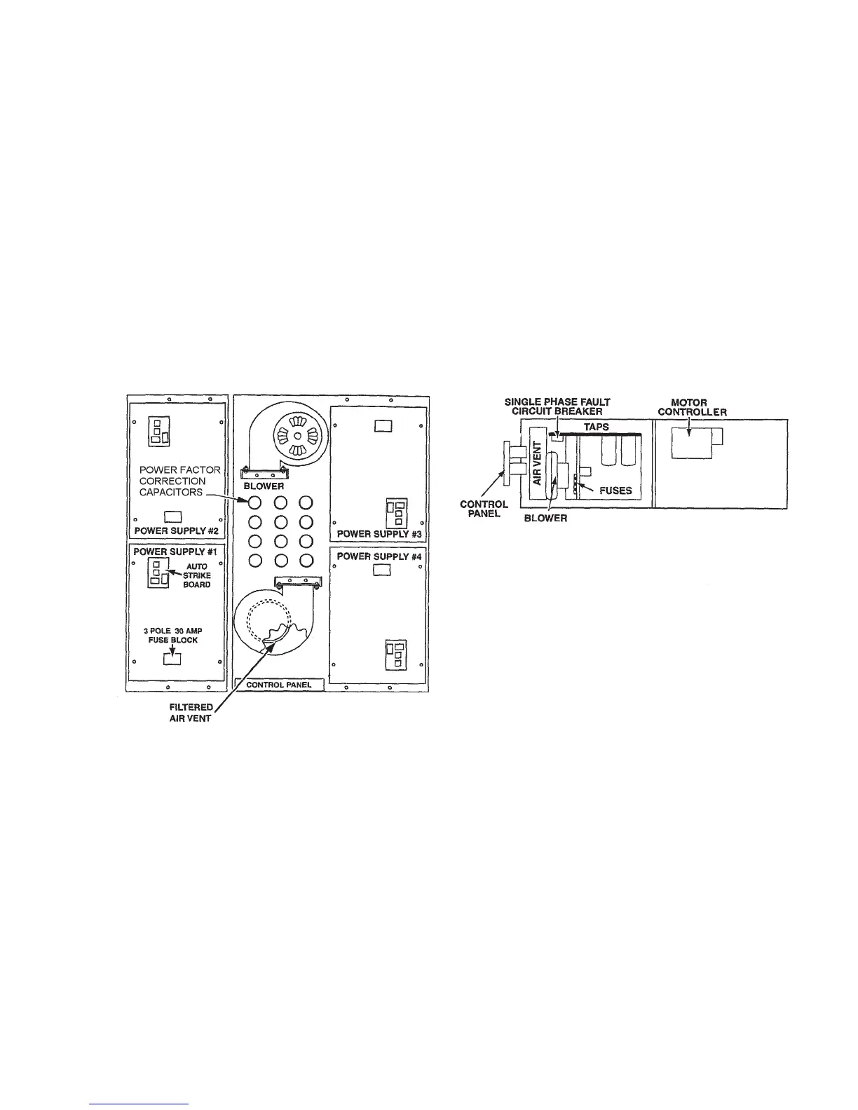
4.0 BASE ASSEMBLY – ELECTRICAL COMPONENTS (see Figures 3 & 4)
To aid in understanding the function of each electrical component, the system is described
belowintheapproximateorderasrelatedtothe“ow”ofelectricitystartingfromtheinput
power connection through the entire system of light and motion.
The Base Assembly contains:
1. Control Panel
2. Main Wire Harness Assembly
3. Motion Drive Motor
4. Cooling System Blower(s)
5. DC Power Supply
FIGURE 3
The base assembly electrical components which provide DC power for operation of the
xenonlight(s)aresituatedinmodulargroup(s)andareidentiedbynumberastowhich
lamphouse they relate to.
Access to the electrical components for servicing can be accomplished by the removal of
the side panels. The access panels can be removed by unscrewing the fasteners located
along the outside edge of the panels.
4.1 CONTROL PANEL
The control panel (see Figures 1 & 2) is mounted in a recessed compartment or rain-tight
box. Access to the control panel components is provided by the removal of four (4) corner
screws and then swinging the panel forward and down. If desired, it may be removed by
unplugging indexed plugs, which connect it to the individual power supplies and internal
components.
7