The various input power cord receptacles, switches, circuit breakers, and hour meter are
mounted to the panel and all electrical connections are accessible from the rear of the
panel. Details of operation are covered in section 3.2.
4.2 MAIN WIRE HARNESS ASSEMBLY
The Wire Harness Assembly provides interconnection between the Control Panel and all
electrical components within the base assembly. Each component may be individually dis-
connected for testing or removal for servicing, by unplugging the indexed connectors from
the Wire Harness Assembly.
4.3 MOTION DRIVE MOTOR
The STX-4 motion drive motor includes a gear-driven speed reduction unit, which operates
on 220/240 volt 60 Hz. input (380/440 volt 50 Hz. in export units) and is activated by the
“motion” switch located on the main control panel. STX-1 units are supplied with a variable
speed DC motor controller.
4.4 COOLING SYSTEM
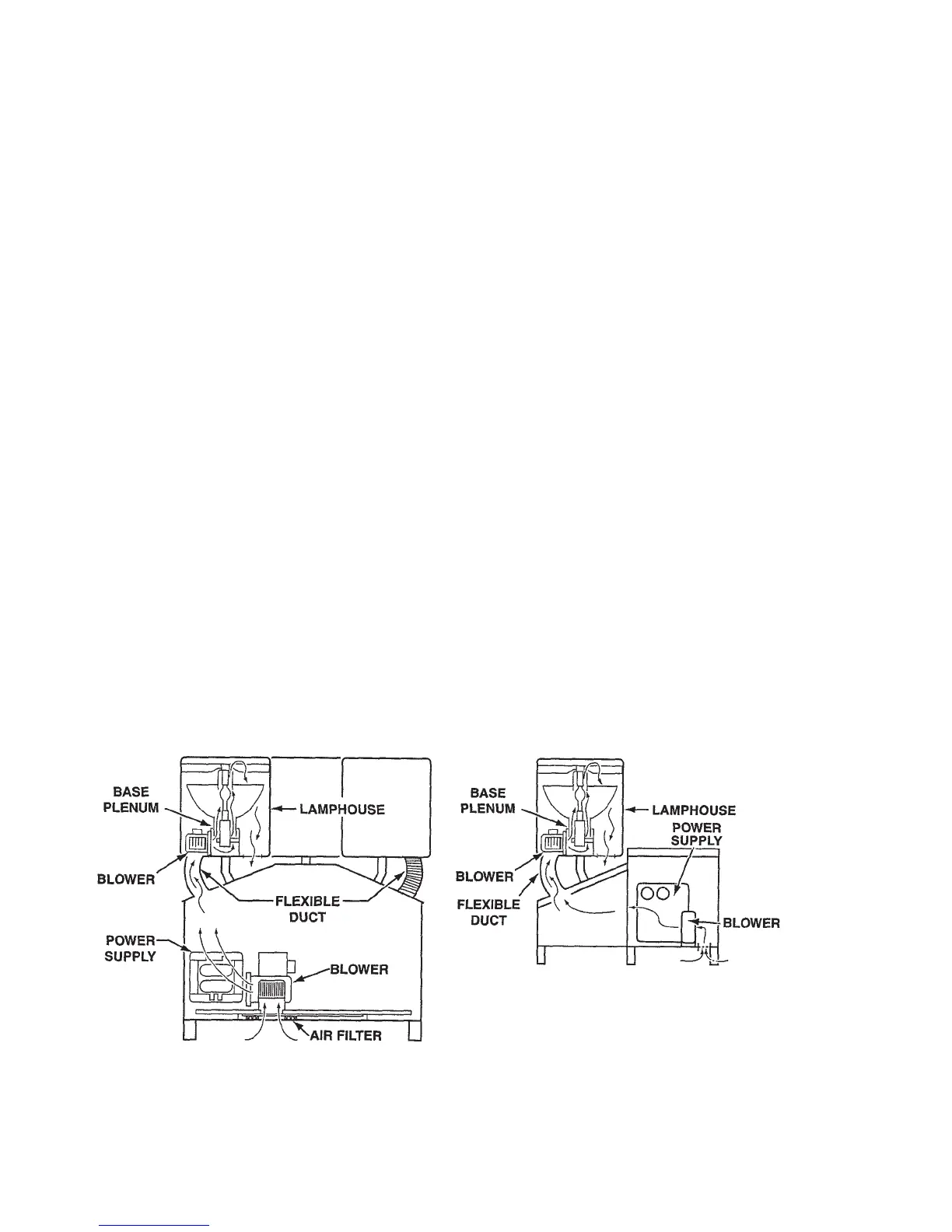
Blower(s)drawcleanairthroughthebottomlteredinlet,pressurizingthebasecabinet.
Theairthenpassesoverthepowersupplies,coolingthem,andcontinuesthroughtheex-
ible ducts to the lamphead(s). With the aid of supplemental blowers in the lampheads, the
air continues through the base plenum, cooling the bulbs. Finally, the air exits out the bot-
tom of the lamphead through screened outlets (see Figure 4).
STX-4 COOLING SYSTEM
STX-1 COOLING SYSTEM
FIGURE 4
8