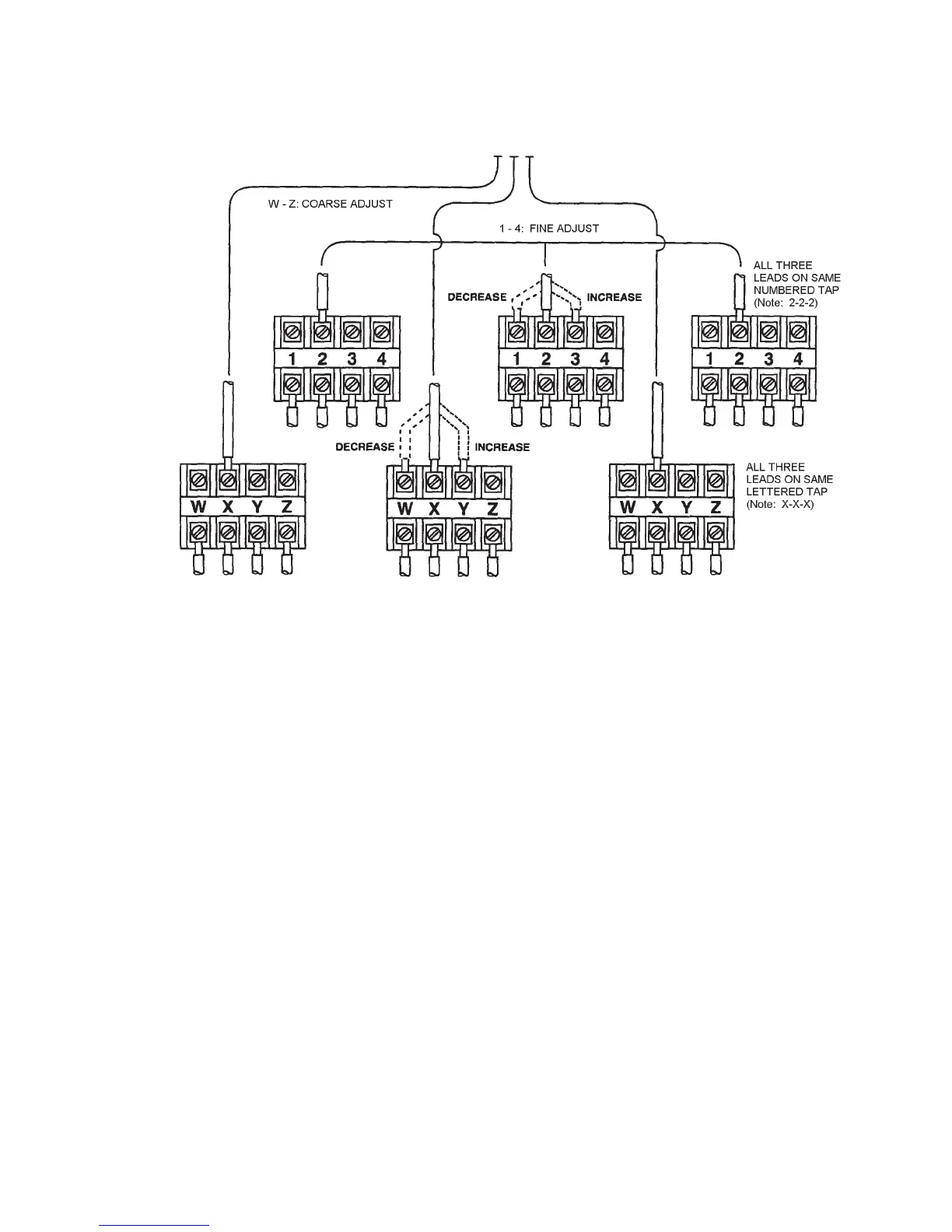
Changing the letter taps (W, X, Y, Z) has a greater effect on voltage. Also, changing the
numbertaps(1,2,3,4)hasasmall“netuning”effect.Thehighestsetting(Z-4)givesthe
highest lamp output and the lowest setting (W-1) gives the lowest lamp output. Taps on the
(6) terminal boards MUST be changed in unison (i.e. three terminal boards set on #2 taps
and three terminal boards set on “X” taps. See Figure 6).
4.5.3 POWER DIODES
Silicon diodes, located on large heat sinks, are attached to each power supply. The diodes
convert the AC to DC, which is necessary for operation of the Xenon lamps. While diodes
are very reliable, they sometimes fail due to voltage surges or “spikes” which sometimes
occur, particularly with improperly regulated generators.
4.5.4 AUTO STRIKE ASSEMBLY – (STX-4 XENON LAMP AUTOMATIC IGNITION)
The Auto Strike Assembly is a module consisting of a printed circuit board and related com-
ponents located near each power supply. Functionally, this circuit activates the igniter circuit
when it senses that the light has been turned on, but the bulb is not drawing any current. It
provides igniter bursts to the lamp and then locks itself out to prevent overloading and po-
tential burn-out of the primary igniter transformer. The auto strike can be re-activated by
ippingthe“Master”switchoffandthenbackonagain.
INPUT FROM
CONTACTOR
VOLTAGE ADJUSTMENT TAPS
(Three Phase)
FIGURE 6
11